Huawei UA5000 Commissioning Manual
Specifications
| Brand | Huawei |
| Model | UA5000 |
| Category | Wireless Access Point |
| File type | Commissioning Manual (PDF) |
| Language | English |
Huawei UA5000 PDF Manual: Read Online
Use the built-in viewer to read the manual online without downloading the PDF.
How to Use This Guide
- Read Online: Scroll down to view the full interactive manual directly in your browser.
- Download PDF: Click the "Download" button to save a high-quality, printable version for offline use.
- Searchable Content: Use Ctrl + F (Cmd + F on Mac) within the online viewer to quickly locate specific error codes, parts lists, or schematics.
Jump to Page


Important Sections from This Manual
Below are selected important pages and sections. Click a page to quickly identify the information you need.
- UA5000 Universal Access Unit Product p. 1
- Copyright © Huawei Technologies Co., Ltd. 2012. All rights reserved. p. 2
- About This Document p. 3
- Command arguments are in italics. p. 4
- 3.5.3 Login in Telnet Mode (Outband Management) p. 5
- About This Document.....................................................................................................................ii p. 6
- 3.11 Detecting the Power on the Optical Port........................................................................................................61 p. 7
- A.4.3 Setting the Default Parameters of the EMU.........................................................................................125 p. 8
- 1 Commissioning Description p. 9
- Commissioning refers to the process of verifying the running of the device, the communication p. 10
- This topic describes how to prepare hardware, software, tools, and data properly to ensure p. 11
- 2 Commissioning Preparations p. 12
- 2.1 Hardware Check p. 13
- Table 2-2 provides the checklist for checking the required software before the commissioning. p. 14
- Straight through cable p. 15
- Networking and data p. 16
- 3 Stand-Alone Commissioning p. 17
- 10. 3.10 Configuring the Networking Mode of the System p. 18
- 3.1 Checking the Settings of Jumpers and DIP Switches p. 19
- The serial port SIO1 is p. 20
- DIP switch S7 is used to set the reporting mode and ratio. Table 3-4 provides the meanings and p. 21
- Table 3-5 Meanings and settings of the H304ESC S4-S8 p. 22
- Table 3-7 Meanings and settings of the H304ESC S3 p. 23
- The available dialing digits of the DIP switch S1 are 8. Table 3-8 provides the meanings and p. 24
- Figure 3-4 Removing and inserting the ESC board p. 25
- Figure 3-5 Layout of the DIP switches on the FCBA board p. 26
- Table 3-9 Description of the DIP switches on the H801FCBB board p. 27
- Table 3-11 Relation between the DIP switch settings and the fan quantity p. 28
- Figure 3-8 Removing/Inserting the fan tray p. 29
- Step 1 Turn on the input power of the DC PDU. p. 30
- 3.4 Commissioning the Power System p. 31
- Step 1 Remove a rectifier unit and check the power supply of the cabinet. p. 32
- The battery capacity parameters corresponding with different cabinets are different. You need p. 33
- The two configured PWX boards must work in the normal state. p. 34
- Step 4 Restore the second power supply (AC power) of the heat exchanger and check the alarm LED p. 35
- Figure 3-10 shows the flowchart for logging in to the UA5000 in the local serial port mode p. 36
- Select the serial port. p. 37
- The baud rate of the HyperTerminal must be the same as the baud rate of the serial port on the p. 38
- Set the line delay and the character delay of the ASCII code. p. 39
- When the text is copied to the HyperTerminal, the Character delay parameter controls the speed at p. 40
- The IP address of the maintenance terminal has been correctly configured. For the process p. 41
- Figure 3-13 shows the flowchart for logging in to and configuring the system through the inband p. 42
- Figure 3-14 Interface of running the telnet application p. 43
- Networking — LAN p. 44
- Figure 3-17 Flowchart for logging in to and configuring the UA5000 through the outband p. 45
- Step 4 Run the telnet application. p. 46
- You must log in to the UA5000 through the local serial port and the IP address and the p. 47
- Figure 3-20 Example network for configuring the inband management over a WAN in SSH p. 48
- Figure 3-21 Flowchart for logging in to and configuring the system in SSH mode p. 49
- l If you log in to the UA5000 through the inband management over a WAN in SSH mode, set p. 50
- l all: The password or RSA key is used for authentication. It indicates that an SSH user can p. 51
- Figure 3-23 Interface of the key generator p. 52
- Figure 3-24 Interface of saving the public key and the private key p. 53
- Figure 3-25 Interface of converting the client public key to the RSA public key p. 54
- Figure 3-26 Interface of the SSH client software p. 55
- The user authentication mode is set to RSA. Therefore, the system displays a message, as p. 56
- Data Plan — SSH Mode p. 58
- Figure 3-31 Flowchart for logging in to and configuring the system in SSH mode p. 59
- l If you log in to the UA5000 through the outband management over a WAN in SSH mode, p. 60
- l rsa: The RSA public key is used for authentication. p. 61
- Figure 3-33 Interface of the key generator p. 62
- Figure 3-34 Interface of saving the public key and the private key p. 63
- Figure 3-35 Interface of converting the client public key to the RSA public key p. 64
- Figure 3-36 Interface of the SSH client software p. 65
- Step 1 In common user mode, run the display language command to check whether the version of the p. 67
- 3.8 Configuring the Board p. 68
- 3.10 Configuring the Networking Mode of the System p. 69
- Do not look into the Tx laser port and the fiber connector on the optical interface board without p. 70
- Step 4 Repeat the preceding steps three times, and then check whether the detected value of the optical p. 71
- Transmission distance (km) p. 72
- Transmission distance (m) p. 73
- Figure 3-40 Detecting the input optical power of an optical port p. 74
- Table 3-20 Technical specifications of the 1000base-Lx port p. 75
- Table 3-22 Technical specifications of the 100Base-Fx port p. 76
- 3.11.3 Detecting the Average Transmit Optical Power of a Single- p. 77
- Figure 3-41 Detecting the transmit optical power of a single-fiber bidirectional optical port p. 78
- Table 3-24 Technical specifications of the 1000base-Lx port p. 79
- Table 3-26 Technical specifications of the 100Base-Fx port p. 80
- Table 3-28 Specifications of the GPON port p. 81
- Prepare properly a calibrated attenuator and an optical power meter. p. 82
- until no packets are lost in a short period (you can ping the peer device on the UA5000 to check p. 83
- Transmit: 1490 nm p. 86
- If the control board is PVMD, and the upstream IPMB board is in slot 3, run the p. 87
- The super user and the administrator have the right to add a user at a lower level, that is: p. 88
- The permitted reenter number determines whether a user name can be p. 89
- Table 3-37 lists the user attributes that can be modified and the related restrictions. p. 90
- When the system is faulty, you can contact the user by querying the appended information p. 91
- 3.15 Checking the System Time p. 92
- 3.16 Commissioning the EMU p. 93
- ESC analog ID: 0 (name: temperature) p. 94
- The HABD shelf supports the configuration of the fan tray through software. p. 95
- Step 1 Adjust the DIP switch of the sub-node for the fan, and p. 96
- Over-frequent data saving affects the system performance. The recommended saving p. 97
- When the database file is saved successfully, the system displays the saving process. p. 98
- Figure 3-43 Running the TFTP application p. 99
- Click OK after the settings. p. 100
- 4 Commissioning the Interconnection p. 101
- 4.1 NMS Interconnection Commissioning p. 102
- Table 4-1 provides the data plan of the outband NMS. p. 103
- Index type MacAddress p. 104
- Figure 4-2 Networking for the inband NMS p. 105
- Device or Port p. 106
- 4.2 Commissioning the MG Interface p. 107
- The UA5000 supports the independent upstream transmission and the integrated upstream transmission p. 108
- huawei(config-if-h248-0)#if-h248 attribute mgip 10.10.10.2 mgport 2944 code text p. 109
- Figure 4-4 Interconnection commissioning networking of the MG interface (over MGCP) p. 110
- Step 1 Add an MG interface. p. 111
- Figure 4-5 shows the example network for commissioning the interconnection with the SIP p. 112
- Upstream VLAN of the media p. 113
- Media IP 10.13.4.116 p. 114
- Figure 4-6 Example network for commissioning the interconnection between the router and the p. 115
- 5 Maintenance and Management p. 116
- 5.1 Checking the Alarm Function and the Event Function p. 117
- Set the upper temperature limit of the p. 118
- Discharge the battery to the under- p. 119
- Table 5-3 Commands for querying history events p. 120
- Step 2 In the common user mode, run the display log command to query the records in the log. p. 121
- A Additional Information p. 122
- A.1 Configuring the IP Address of the Maintenance p. 123
- Step 4 Click Properties to display the Internet Protocol (TCP/IP) Properties dialog box. p. 124
- l Sub-node: 30 p. 125
- A.3.1 Preparing Tools p. 126
- Do not connect the positive and negative polarities of the battery reversely. p. 127
- One hour before the battery charge is over, check the value of the battery voltage one by one. If the battery p. 128
- Medium stream forwarding mode inside a device. 0: p. 129
- Flag of whether AN using the resource unavailable unit p. 130
- Hotline ringing parameters (0~255). For configuring p. 131
- Flag of whether using user-defined ring 15 as default p. 132
- A.4.3 Setting the Default Parameters of the EMU p. 133
- Definition of user-defined alarm indexes p. 134
- Digital Subscriber Line Board p. 135
- Media Gateway Controller p. 136
View Extracted Full Text
UA5000 Universal Access Unit Product
V100R019
Commissioning Guide-PVM CLI
Issue
04
Date
2012-06-25
HUAWEI TECHNOLOGIES CO., LTD.

UA5000 Universal Access Unit Product
V100R019
Commissioning Guide-PVM CLI
Issue
04
Date
2012-06-25
HUAWEI TECHNOLOGIES CO., LTD.

Copyright © Huawei Technologies Co., Ltd. 2012. All rights reserved.
No part of this document may be reproduced or transmitted in any form or by any means without prior written
consent of Huawei Technologies Co., Ltd.
Trademarks and Permissions
 and other Huawei trademarks are trademarks of Huawei Technologies Co., Ltd.
All other trademarks and trade names mentioned in this document are the property of their respective holders.
Notice
The purchased products, services and features are stipulated by the contract made between Huawei and the
customer. All or part of the products, services and features described in this document may not be within the
purchase scope or the usage scope. Unless otherwise specified in the contract, all statements, information,
and recommendations in this document are provided "AS IS" without warranties, guarantees or representations
of any kind, either express or implied.
The information in this document is subject to change without notice. Every effort has been made in the
preparation of this document to ensure accuracy of the contents, but all statements, information, and
recommendations in this document do not constitute the warranty of any kind, express or implied.
Huawei Technologies Co., Ltd.
Address:
Huawei Industrial Base
Bantian, Longgang
Shenzhen 518129
People's Republic of China
Website:
http://www.huawei.com
Email:
[email protected]
Issue 04 (2012-06-25)
Huawei Proprietary and Confidential
Copyright © Huawei Technologies Co., Ltd.
i

Copyright © Huawei Technologies Co., Ltd. 2012. All rights reserved.
No part of this document may be reproduced or transmitted in any form or by any means without prior written
consent of Huawei Technologies Co., Ltd.
Trademarks and Permissions
 and other Huawei trademarks are trademarks of Huawei Technologies Co., Ltd.
All other trademarks and trade names mentioned in this document are the property of their respective holders.
Notice
The purchased products, services and features are stipulated by the contract made between Huawei and the
customer. All or part of the products, services and features described in this document may not be within the
purchase scope or the usage scope. Unless otherwise specified in the contract, all statements, information,
and recommendations in this document are provided "AS IS" without warranties, guarantees or representations
of any kind, either express or implied.
The information in this document is subject to change without notice. Every effort has been made in the
preparation of this document to ensure accuracy of the contents, but all statements, information, and
recommendations in this document do not constitute the warranty of any kind, express or implied.
Huawei Technologies Co., Ltd.
Address:
Huawei Industrial Base
Bantian, Longgang
Shenzhen 518129
People's Republic of China
Website:
http://www.huawei.com
Email:
[email protected]
Issue 04 (2012-06-25)
Huawei Proprietary and Confidential
Copyright © Huawei Technologies Co., Ltd.
i

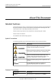
About This Document
Intended Audience
This document describes how to commission and verify the basic functions of the UA5000 from
the aspects of hardware, software, interconnection, and maintenance and management. This
ensures that the device runs stably and reliably on the network.
This document also provides the flow and method of commissioning the UA5000.
This document is intended for:
The installation and commissioning engineers
Symbol Conventions
The following symbols may be found in this document. They are defined as follows
Symbol
Description
Indicates a hazard with a high level of risk which, if not
avoided, will result in death or serious injury.
Indicates a hazard with a medium or low level of risk which,
if not avoided, could result in minor or moderate injury.
Indicates a potentially hazardous situation that, if not
avoided, could cause equipment damage, data loss, and
performance degradation, or unexpected results.
Indicates a tip that may help you solve a problem or save
your time.
Provides additional information to emphasize or
supplement important points of the main text.
Command Conventions
Convention
Description
Boldface
The keywords of a command line are in boldface.
UA5000 Universal Access Unit Product
Commissioning Guide-PVM CLI
About This Document
Issue 04 (2012-06-25)
Huawei Proprietary and Confidential
Copyright © Huawei Technologies Co., Ltd.
ii

About This Document
Intended Audience
This document describes how to commission and verify the basic functions of the UA5000 from
the aspects of hardware, software, interconnection, and maintenance and management. This
ensures that the device runs stably and reliably on the network.
This document also provides the flow and method of commissioning the UA5000.
This document is intended for:
The installation and commissioning engineers
Symbol Conventions
The following symbols may be found in this document. They are defined as follows
Symbol
Description
Indicates a hazard with a high level of risk which, if not
avoided, will result in death or serious injury.
Indicates a hazard with a medium or low level of risk which,
if not avoided, could result in minor or moderate injury.
Indicates a potentially hazardous situation that, if not
avoided, could cause equipment damage, data loss, and
performance degradation, or unexpected results.
Indicates a tip that may help you solve a problem or save
your time.
Provides additional information to emphasize or
supplement important points of the main text.
Command Conventions
Convention
Description
Boldface
The keywords of a command line are in boldface.
UA5000 Universal Access Unit Product
Commissioning Guide-PVM CLI
About This Document
Issue 04 (2012-06-25)
Huawei Proprietary and Confidential
Copyright © Huawei Technologies Co., Ltd.
ii

Convention
Description
Italic
Command arguments are in italics.
[ ]
Items (keywords or arguments) in square brackets [ ] are
optional.
{ x | y | ... }
Alternative items are grouped in braces and separated by
vertical bars. One is selected.
[ x | y | ... ]
Optional alternative items are grouped in square brackets
and separated by vertical bars. One or none is selected.
{ x | y | ... } *
Alternative items are grouped in braces and separated by
vertical bars. A minimum of one or a maximum of all can
be selected.
GUI Conventions
Convention
Description
Boldface
Buttons, menus, parameters, tabs, window, and dialog titles
are in boldface. For example, click OK.
>
Multi-level menus are in boldface and separated by the ">"
signs. For example, choose File > Create > Folder.
Update History
Updates between document issues are cumulative. Therefore, the latest document issue contains
all updates made in previous issues.
Updates in Issue 04 (2012-06-25)
Based on issue 03 (2012-02-25), the document is updated as follows:
Modified:
l
3.5.1 Login in the Local Serial Port Mode
l
3.5.2 Login in Telnet Mode (Inband Management)
l
3.5.3 Login in Telnet Mode (Outband Management)
l
3.5.4 Login in SSH Mode (Inband Management)
l
3.5.5 Login in SSH Mode (Outband Management)
Updates in Issue 03 (2012-02-25)
Based on issue 02 (2010-06-25), the document is updated as follows:
UA5000 Universal Access Unit Product
Commissioning Guide-PVM CLI
About This Document
Issue 04 (2012-06-25)
Huawei Proprietary and Confidential
Copyright © Huawei Technologies Co., Ltd.
iii

Convention
Description
Italic
Command arguments are in italics.
[ ]
Items (keywords or arguments) in square brackets [ ] are
optional.
{ x | y | ... }
Alternative items are grouped in braces and separated by
vertical bars. One is selected.
[ x | y | ... ]
Optional alternative items are grouped in square brackets
and separated by vertical bars. One or none is selected.
{ x | y | ... } *
Alternative items are grouped in braces and separated by
vertical bars. A minimum of one or a maximum of all can
be selected.
GUI Conventions
Convention
Description
Boldface
Buttons, menus, parameters, tabs, window, and dialog titles
are in boldface. For example, click OK.
>
Multi-level menus are in boldface and separated by the ">"
signs. For example, choose File > Create > Folder.
Update History
Updates between document issues are cumulative. Therefore, the latest document issue contains
all updates made in previous issues.
Updates in Issue 04 (2012-06-25)
Based on issue 03 (2012-02-25), the document is updated as follows:
Modified:
l
3.5.1 Login in the Local Serial Port Mode
l
3.5.2 Login in Telnet Mode (Inband Management)
l
3.5.3 Login in Telnet Mode (Outband Management)
l
3.5.4 Login in SSH Mode (Inband Management)
l
3.5.5 Login in SSH Mode (Outband Management)
Updates in Issue 03 (2012-02-25)
Based on issue 02 (2010-06-25), the document is updated as follows:
UA5000 Universal Access Unit Product
Commissioning Guide-PVM CLI
About This Document
Issue 04 (2012-06-25)
Huawei Proprietary and Confidential
Copyright © Huawei Technologies Co., Ltd.
iii

Modified:
l
3.5.3 Login in Telnet Mode (Outband Management)
l
4.4 Commissioning the Interconnection Between the Device and the Router
l
A.4.1 Setting the Default System Parameters
l
A.4.2 Setting the Default Overseas Parameters
Updates in Issue 02 (2010-06-25)
The structure and content of the document are optimized comprehensively so that the document
can better cater to user preferences and guide users.
Updates in Issue 01 (2009-12-31)
This is the first release.
UA5000 Universal Access Unit Product
Commissioning Guide-PVM CLI
About This Document
Issue 04 (2012-06-25)
Huawei Proprietary and Confidential
Copyright © Huawei Technologies Co., Ltd.
iv

Modified:
l
3.5.3 Login in Telnet Mode (Outband Management)
l
4.4 Commissioning the Interconnection Between the Device and the Router
l
A.4.1 Setting the Default System Parameters
l
A.4.2 Setting the Default Overseas Parameters
Updates in Issue 02 (2010-06-25)
The structure and content of the document are optimized comprehensively so that the document
can better cater to user preferences and guide users.
Updates in Issue 01 (2009-12-31)
This is the first release.
UA5000 Universal Access Unit Product
Commissioning Guide-PVM CLI
About This Document
Issue 04 (2012-06-25)
Huawei Proprietary and Confidential
Copyright © Huawei Technologies Co., Ltd.
iv

Contents
About This Document.....................................................................................................................ii
1 Commissioning Description.......................................................................................................1
1.1 Definition............................................................................................................................................................2
1.2 Commissioning Flow..........................................................................................................................................2
2 Commissioning Preparations......................................................................................................4
2.1 Hardware Check.................................................................................................................................................5
2.2 Software Requirements.......................................................................................................................................5
2.3 Tool Requirements.............................................................................................................................................6
2.4 Data Requirements.............................................................................................................................................7
3 Stand-Alone Commissioning......................................................................................................9
3.1 Checking the Settings of Jumpers and DIP Switches.......................................................................................11
3.1.1 Checking the Settings of DIP Switches and Jumpers of Environment Monitoring Boards....................11
3.1.2 Checking the DIP Settings on the Monitoring Board of the Fan.............................................................17
3.2 Powering On the Indoor Device.......................................................................................................................21
3.3 Powering On the Outdoor Device....................................................................................................................22
3.4 Commissioning the Power System...................................................................................................................23
3.4.1 Checking the Power Supply of DC PDU.................................................................................................23
3.4.2 Checking the Power Supply of AC Power Module.................................................................................23
3.4.3 Configuring the Battery and Checking the Power Supply of the Battery................................................24
3.4.4 Checking the Power Supply of the Power Board ...................................................................................25
3.4.5 Checking the Power Supply of the Heat Exchanger................................................................................26
3.5 Logging in to the System..................................................................................................................................27
3.5.1 Login in the Local Serial Port Mode.......................................................................................................27
3.5.2 Login in Telnet Mode (Inband Management).........................................................................................32
3.5.3 Login in Telnet Mode (Outband Management).......................................................................................35
3.5.4 Login in SSH Mode (Inband Management)............................................................................................38
3.5.5 Login in SSH Mode (Outband Management)..........................................................................................48
3.6 Checking the Software Version........................................................................................................................58
3.7 Adding a Shelf..................................................................................................................................................59
3.8 Configuring the Board......................................................................................................................................60
3.9 Loading the Script............................................................................................................................................60
3.10 Configuring the Networking Mode of the System.........................................................................................61
UA5000 Universal Access Unit Product
Commissioning Guide-PVM CLI
Contents
Issue 04 (2012-06-25)
Huawei Proprietary and Confidential
Copyright © Huawei Technologies Co., Ltd.
v

Contents
About This Document.....................................................................................................................ii
1 Commissioning Description.......................................................................................................1
1.1 Definition............................................................................................................................................................2
1.2 Commissioning Flow..........................................................................................................................................2
2 Commissioning Preparations......................................................................................................4
2.1 Hardware Check.................................................................................................................................................5
2.2 Software Requirements.......................................................................................................................................5
2.3 Tool Requirements.............................................................................................................................................6
2.4 Data Requirements.............................................................................................................................................7
3 Stand-Alone Commissioning......................................................................................................9
3.1 Checking the Settings of Jumpers and DIP Switches.......................................................................................11
3.1.1 Checking the Settings of DIP Switches and Jumpers of Environment Monitoring Boards....................11
3.1.2 Checking the DIP Settings on the Monitoring Board of the Fan.............................................................17
3.2 Powering On the Indoor Device.......................................................................................................................21
3.3 Powering On the Outdoor Device....................................................................................................................22
3.4 Commissioning the Power System...................................................................................................................23
3.4.1 Checking the Power Supply of DC PDU.................................................................................................23
3.4.2 Checking the Power Supply of AC Power Module.................................................................................23
3.4.3 Configuring the Battery and Checking the Power Supply of the Battery................................................24
3.4.4 Checking the Power Supply of the Power Board ...................................................................................25
3.4.5 Checking the Power Supply of the Heat Exchanger................................................................................26
3.5 Logging in to the System..................................................................................................................................27
3.5.1 Login in the Local Serial Port Mode.......................................................................................................27
3.5.2 Login in Telnet Mode (Inband Management).........................................................................................32
3.5.3 Login in Telnet Mode (Outband Management).......................................................................................35
3.5.4 Login in SSH Mode (Inband Management)............................................................................................38
3.5.5 Login in SSH Mode (Outband Management)..........................................................................................48
3.6 Checking the Software Version........................................................................................................................58
3.7 Adding a Shelf..................................................................................................................................................59
3.8 Configuring the Board......................................................................................................................................60
3.9 Loading the Script............................................................................................................................................60
3.10 Configuring the Networking Mode of the System.........................................................................................61
UA5000 Universal Access Unit Product
Commissioning Guide-PVM CLI
Contents
Issue 04 (2012-06-25)
Huawei Proprietary and Confidential
Copyright © Huawei Technologies Co., Ltd.
v

3.11 Detecting the Power on the Optical Port........................................................................................................61
3.11.1 Detecting the Average Transmit Power of the Two-Fiber Bidirectional Optical Port..........................61
3.11.2 Detecting the Actual Input Power of the Two-Fiber Bidirectional Optical Port...................................65
3.11.3 Detecting the Average Transmit Optical Power of a Single-Fiber Bidirectional Optical Port.............69
3.11.4 Detecting the Actual Input Power of a Single-Fiber Bidirectional Optical Port...................................73
3.12 Checking the Status of the Uplink Port..........................................................................................................78
3.13 Changing the System Name...........................................................................................................................79
3.14 Configuring a System User.............................................................................................................................79
3.14.1 Adding a System User...........................................................................................................................79
3.14.2 Modifying the System User Attributes..................................................................................................81
3.15 Checking the System Time.............................................................................................................................84
3.16 Commissioning the EMU...............................................................................................................................85
3.16.1 Commissioning the ESC EMU..............................................................................................................85
3.16.2 Commissioning the Fan EMU...............................................................................................................86
3.17 Checking the Auto-Save Settings...................................................................................................................88
3.18 Saving the Data...............................................................................................................................................89
3.19 Backing Up the System File...........................................................................................................................90
4 Commissioning the Interconnection.......................................................................................93
4.1 NMS Interconnection Commissioning.............................................................................................................94
4.1.1 Commissioning the Outband NMS..........................................................................................................94
4.1.2 Commissioning the Inband NMS............................................................................................................96
4.2 Commissioning the MG Interface....................................................................................................................99
4.2.1 Commissioning the MG Interface (Through H.248)...............................................................................99
4.2.2 Commissioning the MG Interface Connection (Through MGCP)........................................................101
4.3 Commissioning the Interconnection with the SIP Interface...........................................................................103
4.4 Commissioning the Interconnection Between the Device and the Router.....................................................106
5 Maintenance and Management Commissioning................................................................108
5.1 Checking the Alarm Function and the Event Function..................................................................................109
5.1.1 Verifying the Alarm Function and the Event Function.........................................................................109
5.1.2 Querying Alarms and Events.................................................................................................................111
5.2 Checking the Log............................................................................................................................................112
A Additional Information...........................................................................................................114
A.1 Configuring the IP Address of the Maintenance Terminal............................................................................115
A.2 Making a Script..............................................................................................................................................116
A.3 Operation Guide on Battery Supplementary Charge.....................................................................................117
A.3.1 Preparing Tools.....................................................................................................................................118
A.3.2 Precautions............................................................................................................................................118
A.3.3 Operation Process.................................................................................................................................119
A.4 Software Package Settings.............................................................................................................................120
A.4.1 Setting the Default System Parameters.................................................................................................120
A.4.2 Setting the Default Overseas Parameters..............................................................................................121
UA5000 Universal Access Unit Product
Commissioning Guide-PVM CLI
Contents
Issue 04 (2012-06-25)
Huawei Proprietary and Confidential
Copyright © Huawei Technologies Co., Ltd.
vi

3.11 Detecting the Power on the Optical Port........................................................................................................61
3.11.1 Detecting the Average Transmit Power of the Two-Fiber Bidirectional Optical Port..........................61
3.11.2 Detecting the Actual Input Power of the Two-Fiber Bidirectional Optical Port...................................65
3.11.3 Detecting the Average Transmit Optical Power of a Single-Fiber Bidirectional Optical Port.............69
3.11.4 Detecting the Actual Input Power of a Single-Fiber Bidirectional Optical Port...................................73
3.12 Checking the Status of the Uplink Port..........................................................................................................78
3.13 Changing the System Name...........................................................................................................................79
3.14 Configuring a System User.............................................................................................................................79
3.14.1 Adding a System User...........................................................................................................................79
3.14.2 Modifying the System User Attributes..................................................................................................81
3.15 Checking the System Time.............................................................................................................................84
3.16 Commissioning the EMU...............................................................................................................................85
3.16.1 Commissioning the ESC EMU..............................................................................................................85
3.16.2 Commissioning the Fan EMU...............................................................................................................86
3.17 Checking the Auto-Save Settings...................................................................................................................88
3.18 Saving the Data...............................................................................................................................................89
3.19 Backing Up the System File...........................................................................................................................90
4 Commissioning the Interconnection.......................................................................................93
4.1 NMS Interconnection Commissioning.............................................................................................................94
4.1.1 Commissioning the Outband NMS..........................................................................................................94
4.1.2 Commissioning the Inband NMS............................................................................................................96
4.2 Commissioning the MG Interface....................................................................................................................99
4.2.1 Commissioning the MG Interface (Through H.248)...............................................................................99
4.2.2 Commissioning the MG Interface Connection (Through MGCP)........................................................101
4.3 Commissioning the Interconnection with the SIP Interface...........................................................................103
4.4 Commissioning the Interconnection Between the Device and the Router.....................................................106
5 Maintenance and Management Commissioning................................................................108
5.1 Checking the Alarm Function and the Event Function..................................................................................109
5.1.1 Verifying the Alarm Function and the Event Function.........................................................................109
5.1.2 Querying Alarms and Events.................................................................................................................111
5.2 Checking the Log............................................................................................................................................112
A Additional Information...........................................................................................................114
A.1 Configuring the IP Address of the Maintenance Terminal............................................................................115
A.2 Making a Script..............................................................................................................................................116
A.3 Operation Guide on Battery Supplementary Charge.....................................................................................117
A.3.1 Preparing Tools.....................................................................................................................................118
A.3.2 Precautions............................................................................................................................................118
A.3.3 Operation Process.................................................................................................................................119
A.4 Software Package Settings.............................................................................................................................120
A.4.1 Setting the Default System Parameters.................................................................................................120
A.4.2 Setting the Default Overseas Parameters..............................................................................................121
UA5000 Universal Access Unit Product
Commissioning Guide-PVM CLI
Contents
Issue 04 (2012-06-25)
Huawei Proprietary and Confidential
Copyright © Huawei Technologies Co., Ltd.
vi

A.4.3 Setting the Default Parameters of the EMU.........................................................................................125
A.5 Acronyms and Abbreviations........................................................................................................................126
UA5000 Universal Access Unit Product
Commissioning Guide-PVM CLI
Contents
Issue 04 (2012-06-25)
Huawei Proprietary and Confidential
Copyright © Huawei Technologies Co., Ltd.
vii

A.4.3 Setting the Default Parameters of the EMU.........................................................................................125
A.5 Acronyms and Abbreviations........................................................................................................................126
UA5000 Universal Access Unit Product
Commissioning Guide-PVM CLI
Contents
Issue 04 (2012-06-25)
Huawei Proprietary and Confidential
Copyright © Huawei Technologies Co., Ltd.
vii

1 Commissioning Description
About This Chapter
This topic describes the definition, prerequisites, and flow of the commissioning.
1.1 Definition
Commissioning refers to the process of verifying the running of the device, the communication
of the device with the NMS and other interconnected devices, and ensuring that the device can
be used as required.
1.2 Commissioning Flow
This topic provides the prerequisites and basic flow for commissioning the device.
UA5000 Universal Access Unit Product
Commissioning Guide-PVM CLI
1 Commissioning Description
Issue 04 (2012-06-25)
Huawei Proprietary and Confidential
Copyright © Huawei Technologies Co., Ltd.
1

1 Commissioning Description
About This Chapter
This topic describes the definition, prerequisites, and flow of the commissioning.
1.1 Definition
Commissioning refers to the process of verifying the running of the device, the communication
of the device with the NMS and other interconnected devices, and ensuring that the device can
be used as required.
1.2 Commissioning Flow
This topic provides the prerequisites and basic flow for commissioning the device.
UA5000 Universal Access Unit Product
Commissioning Guide-PVM CLI
1 Commissioning Description
Issue 04 (2012-06-25)
Huawei Proprietary and Confidential
Copyright © Huawei Technologies Co., Ltd.
1

1.1 Definition
Commissioning refers to the process of verifying the running of the device, the communication
of the device with the NMS and other interconnected devices, and ensuring that the device can
be used as required.
1.2 Commissioning Flow
This topic provides the prerequisites and basic flow for commissioning the device.
NOTE
This flow is for the commissioning procedures in newly-created offices. For the existing offices, adjust the
commissioning procedures and contents according to the actual situation.
Prerequisites
The hardware installation personnel must have installed and checked the UA5000 hardware.
Flowchart
This document describes how to commission the UA5000 in the following steps.
Figure 1-1 provides the commissioning flowchart.
Figure 1-1 Commissioning flowchart
End
Start
Commissioing
preparations
Stand-alone
commissioning
Interconnection
Commissioning
Maintenance and management
commissioning
The following topics provide a brief description about the contents of each chapter:
UA5000 Universal Access Unit Product
Commissioning Guide-PVM CLI
1 Commissioning Description
Issue 04 (2012-06-25)
Huawei Proprietary and Confidential
Copyright © Huawei Technologies Co., Ltd.
2

1.1 Definition
Commissioning refers to the process of verifying the running of the device, the communication
of the device with the NMS and other interconnected devices, and ensuring that the device can
be used as required.
1.2 Commissioning Flow
This topic provides the prerequisites and basic flow for commissioning the device.
NOTE
This flow is for the commissioning procedures in newly-created offices. For the existing offices, adjust the
commissioning procedures and contents according to the actual situation.
Prerequisites
The hardware installation personnel must have installed and checked the UA5000 hardware.
Flowchart
This document describes how to commission the UA5000 in the following steps.
Figure 1-1 provides the commissioning flowchart.
Figure 1-1 Commissioning flowchart
End
Start
Commissioing
preparations
Stand-alone
commissioning
Interconnection
Commissioning
Maintenance and management
commissioning
The following topics provide a brief description about the contents of each chapter:
UA5000 Universal Access Unit Product
Commissioning Guide-PVM CLI
1 Commissioning Description
Issue 04 (2012-06-25)
Huawei Proprietary and Confidential
Copyright © Huawei Technologies Co., Ltd.
2

1.
Commissioning Preparations
This topic describes how to prepare hardware, software, tools, and data properly to ensure
that the commissioning is implemented normally.
2.
Stand-Alone Commissioning
This topic describes how to commission the stand-alone UA5000 after the hardware
installation so that the stand-alone UA5000 can work in the normal state.
3.
Interconnection Commissioning
The administrator can maintain and manage the UA5000 in inband network management
or outband network management mode. This topic describes how to commission the
interconnection by considering the "iManager U2000 unified network management
system" (iManager U2000) as an example.
4.
Maintenance and Management Commissioning
This topic describes how to verify the reliability of the device after commissioning the basic
functions and services of the device to ensure the performance reliability of the UA5000.
UA5000 Universal Access Unit Product
Commissioning Guide-PVM CLI
1 Commissioning Description
Issue 04 (2012-06-25)
Huawei Proprietary and Confidential
Copyright © Huawei Technologies Co., Ltd.
3

2 Commissioning Preparations
About This Chapter
This topic describes how to prepare hardware, software, tools, and data properly to ensure that
the commissioning is implemented normally.
2.1 Hardware Check
This topic describes how to check the hardware before the commissioning. Make sure that the
hardware is available and check the hardware before the commissioning to facilitate the
subsequent operations.
2.2 Software Requirements
This topic describes the software requirements for the commissioning. You need to prepare the
commissioning software before the commissioning to facilitate the subsequent operations.
2.3 Tool Requirements
This topic describes the tools required for the commissioning. You need to prepare and check
the required tools before the commissioning to facilitate the subsequent operations.
2.4 Data Requirements
This topic describes the data requirements for the commissioning. The information about
hardware configuration, networking, and data plan must be available for data configuration.
UA5000 Universal Access Unit Product
Commissioning Guide-PVM CLI
2 Commissioning Preparations
Issue 04 (2012-06-25)
Huawei Proprietary and Confidential
Copyright © Huawei Technologies Co., Ltd.
4

2.1 Hardware Check
This topic describes how to check the hardware before the commissioning. Make sure that the
hardware is available and check the hardware before the commissioning to facilitate the
subsequent operations.
Checklist
Table 2-1 provides the checklist for checking the hardware before the commissioning.
Table 2-1 Hardware checklist
No.
Item
Description
1
Power and
grounding
l Ensure that the power cable and the ground cable are properly
connected.
l Ensure that the power cable, ground cable, and power
distribution switch are labeled correctly, clearly and orderly.
l Ensure that the connectors of external ground cables and
protection ground cables of the cabinet are properly
connected, and they are not damaged.
l Ensure that the power supply of the device is in the normal
state.
2
Cables and
connectors
l Ensure that the cable connectors are tight and firm.
l Ensure that the cable jacket is intact.
l Ensure that the cable labels are clear and neat.
l Ensure that cables are bundled reliably.
3
Upper layer
device
l Check the physical position of the interconnection port on the
upper layer device.
l Ensure that the upper layer device works in the normal state
and can be used for commissioning.
NOTE
The hardware installation personnel must check the device according to items "Power and grounding" and
"Cables and connectors" in Table 2-1 when performing the installation check. The commissioning
personnel can check these two items again to ensure that the hardware connection is reliable during the
commissioning.
2.2 Software Requirements
This topic describes the software requirements for the commissioning. You need to prepare the
commissioning software before the commissioning to facilitate the subsequent operations.
UA5000 Universal Access Unit Product
Commissioning Guide-PVM CLI
2 Commissioning Preparations
Issue 04 (2012-06-25)
Huawei Proprietary and Confidential
Copyright © Huawei Technologies Co., Ltd.
5

Checklist
Table 2-2 provides the checklist for checking the required software before the commissioning.
Table 2-2 Software checklist
No.
Item
Description
1
Software
package
Check whether the software package for the commissioning is
complete and the version is correct.
2
Software
commissioning
tools
Check whether the required software commissioning tools are
available. The commonly used commissioning tools are as
follows:
l HyperTerminal: Used for logging in to the UA5000
through the CLI. The tool is embedded in Windows.
l TFTP and FTP: Used for loading software, which can be
downloaded from http://support.huawei.com.
l Toolbox: Used for tracing signals. It is released with the
version.
2.3 Tool Requirements
This topic describes the tools required for the commissioning. You need to prepare and check
the required tools before the commissioning to facilitate the subsequent operations.
Checklist
Table 2-3 provides the checklist for checking the required tools before the commissioning.
Table 2-3 Tool checklist
No.
Item
Description
Remarks
1
Cables
RS-232 serial port cable:
l One end is an RJ45 connector,
used for connecting to the
control board of the device.
l The other end is a DB-9 or
DB-25 female connector, used
for connecting to the
commissioning terminal. When
the maintenance terminal is a
PC, use the DB-9 female
connector.
Used for connecting the
commissioning terminal to the
UA5000 in the case of maintenance
through the serial port.
Crossover cable
Used for connecting the
commissioning terminal to the
UA5000 in the case of maintenance
in the Telnet mode.
UA5000 Universal Access Unit Product
Commissioning Guide-PVM CLI
2 Commissioning Preparations
Issue 04 (2012-06-25)
Huawei Proprietary and Confidential
Copyright © Huawei Technologies Co., Ltd.
6

No.
Item
Description
Remarks
Straight through cable
Used for commissioning the
services.
Tail fiber
Used for detecting the optical
power and optical sensitivity, and
transmitting the service upstream.
2
Maintain
ing
terminal
(Generally) Portable computer with
HyperTerminal application
Used for logging in to the
UA5000 to commission the
UA5000.
3
Auxiliar
y device
and
meter
Optical power meter
Used for the following tests on the
optical port: actual receive optical
power test, receive sensitivity test,
and overload optical power test.
Adjustable optical attenuator
Used on the optical signal receive
port for attenuating the received
optical signal during the device
commissioning to protect the
optical port from being damaged by
strong optical power.
Multimeter
Used for measuring the voltage,
resistance, and current intensity
during the power commissioning.
2.4 Data Requirements
This topic describes the data requirements for the commissioning. The information about
hardware configuration, networking, and data plan must be available for data configuration.
Checklist
Before the commissioning, collect the information about the hardware configuration,
networking, and data plan based on the engineering documents such as the project division layout
and network design. Table 2-4 provides the data requirement checklist.
Table 2-4 Checklist
No.
Item
Description
1
Hardware
configuration
It includes but is not limited to:
l The type of the control board and other boards, and the
slot layout.
l The type of the uplink port and service port, and their
physical locations.
UA5000 Universal Access Unit Product
Commissioning Guide-PVM CLI
2 Commissioning Preparations
Issue 04 (2012-06-25)
Huawei Proprietary and Confidential
Copyright © Huawei Technologies Co., Ltd.
7

No.
Item
Description
2
Networking and data
plan
It includes but is not limited to:
l Network topology
l IP address allocation
l VLAN plan
l Service type and data plan
UA5000 Universal Access Unit Product
Commissioning Guide-PVM CLI
2 Commissioning Preparations
Issue 04 (2012-06-25)
Huawei Proprietary and Confidential
Copyright © Huawei Technologies Co., Ltd.
8

3 Stand-Alone Commissioning
About This Chapter
This topic describes how to commission the stand-alone UA5000 after the hardware installation
so that the stand-alone UA5000 can work in the normal state.
1.
3.1 Checking the Settings of Jumpers and DIP Switches
This topic describes how to check the settings of the environment supervision circuit (ESC)
board, fan EMU jumpers and dual-in-line package (DIP) switches so that the settings
conform to the actual application.
2.
3.2 Powering On the Indoor Device
This topic describes how to power on the indoor device to ensure that each board is supplied
with power in the normal state.
3.
3.3 Powering On the Outdoor Device
This topic describes how to power on the outdoor device to ensure that each board is
supplied with power in the normal state.
4.
3.4 Commissioning the Power System
This topic describes how to commission the reliability of the power supply system so that
the system can supply the power to the device in the normal state.
5.
3.5 Logging in to the System
This topic describes how to log in to theUA5000 and then commission the UA5000 through
the maintenance terminal.
6.
3.6 Checking the Software Version
This topic describes how to check whether the version of the running software meets the
requirements for office deployment.
7.
3.7 Adding a Shelf
This topic describes how to add a shelf (including the master shelf and the slave shelf) to
ensure the normal running of the shelf.
8.
3.8 Configuring the Board
This topic describes how to check whether the inserted board is the same as the board
required in the data plan and check whether the board runs in the normal state.
9.
3.9 Loading the Script
This topic describes how to load the script file to configure the basic data of the device,
which is a preparation for the commissioning of the basic functions of the device.
UA5000 Universal Access Unit Product
Commissioning Guide-PVM CLI
3 Stand-Alone Commissioning
Issue 04 (2012-06-25)
Huawei Proprietary and Confidential
Copyright © Huawei Technologies Co., Ltd.
9

10. 3.10 Configuring the Networking Mode of the System
When the networking modes of the UA5000 are different, perform the operation to
configure the networking mode of the system to independent networking or integrated
access networking.
11. 3.11 Detecting the Power on the Optical Port
This topic describes how to detect the mean launched optical power and the actual input
optical power to check whether the transmit optical transceiver and the receive optical
transceiver are in the normal state.
12. 3.12 Checking the Status of the Uplink Port
This topic describes how to check the status of the uplink port to ensure that the
interconnection between the UA5000 and the upper layer device is in the normal state, thus
ensuring the normal communication.
13. 3.13 Changing the System Name
This topic describes how to customize the useful system name to differentiate UA5000s.
This facilitates the management of the UA5000.
14. 3.14 Configuring a System User
When accessing, configuring, and managing the UA5000, you need to add the system
operation users with different attributes. This topic describes how to add system operation
users and modify the attributes of the system operation users.
15. 3.15 Checking the System Time
This topic describes how to check whether the system time, time zone, time stamp, and
start and end Daylight Saving Time (DST) of the UA5000 are consistent with the actual
conditions.
16. 3.16 Commissioning the EMU
The UA5000 provides the function of monitoring various environment parameters (such
as the temperature, humidity, and power voltage) so that the device runs in the stable
environment. This topic describes how to commission the environment monitoring unit
(EMU).
17. 3.17 Checking the Auto-Save Settings
This topic describes how to check the settings of the auto-save function to prevent data loss
due to reboots.
18. 3.18 Saving the Data
This topic describes how to save the data into the flash memory to prevent data loss due to
reboots.
19. 3.19 Backing Up the System File
This topic describes how to back up the system file to prevent permanent data loss due to
the system failure. At the first office deployment or when the upgrade is complete, you
need to back up the database file and the configuration file to restore the system in the case
of the system failure.
UA5000 Universal Access Unit Product
Commissioning Guide-PVM CLI
3 Stand-Alone Commissioning
Issue 04 (2012-06-25)
Huawei Proprietary and Confidential
Copyright © Huawei Technologies Co., Ltd.
10

3.1 Checking the Settings of Jumpers and DIP Switches
This topic describes how to check the settings of the environment supervision circuit (ESC)
board, fan EMU jumpers and dual-in-line package (DIP) switches so that the settings conform
to the actual application.
3.1.1 Checking the Settings of DIP Switches and Jumpers of
Environment Monitoring Boards
This topic describes how to check the settings of the jumpers on the ESC board and the dual-in-
line package (DIP) switches. This ensures that the settings conform to the actual application.
Prerequisites
The UA5000 must be disconnected from the power supply.
Jumpers and DIP Switches of H303ESC
The H303ESC board is located on the right side of the environment monitoring unit (EMU).
The H303ESC board provides six jumpers, namely the S1, S2, S3, S8, S10, and S11, and two
DIP switches S6 and S7. The S5 is the shielding switch of the board alarm buzzer, which is
enabled by default, as shown in Figure 3-1.
Figure 3-1 Layout of jumpers on the H303ESC board and DIP switches
H303ESC
S11
D1
S5
ON
OFF
S6
S1
S2
S10
S3
S8
1 2 3
1234 5678
ON
OFF
S7
1234
Jumpers S1, S2, S3, S8 and S10 are used to set the type of the serial port. Table 3-1 provides
their meanings and settings.
Table 3-1 Meanings and settings of the H303ESC S1, S2, S3, S8, and S10
Jumper
Settings
Meanings
Default Settings
S1
1-2 connected
The serial port SIO1 is
RS-232.
2-3 connected
UA5000 Universal Access Unit Product
Commissioning Guide-PVM CLI
3 Stand-Alone Commissioning
Issue 04 (2012-06-25)
Huawei Proprietary and Confidential
Copyright © Huawei Technologies Co., Ltd.
11

Jumper
Settings
Meanings
Default Settings
2-3 connected
The serial port SIO1 is
RS-422.
S2
1-2 connected
The serial port SIO2 is
RS-232.
2-3 connected
2-3 connected
The serial port SIO2 is
RS-422.
S3, S8,
and S10
1-2 of S3, S8, and S10
connected
The serial port SIO3 is
RS-232.
1-2 of all jumpers
connected
2-3 of S2 connected; 1-2 of
S8 and S10 connected
The serial port SIO3 is
RS-422.
2-3 of S8 and S10 connected,
S3 connected unlimited
The serial port SIO3 is
RS-485.
S11 is used to check whether the running LED on the front panel is valid. Table 3-2 provides
the meanings and settings of S11.
Table 3-2 Meanings and settings of the H303ESC S11
Jumper
Settings
Meanings
Default
Settings
S11
1-2 connected
The running LED on the board
is valid.
1-2 connected
2-3 connected
The running LED on the board
is invalid.
DIP switch S6 is used to set the type of external analog sensors. Table 3-3 provides the meanings
and settings of S6.
Table 3-3 Meanings and settings of the H303ESC S6
DIP Switch
Settings
Meanings
Default
Settings
S6-1 to S6-6
ON
The external analog sensor is of the
current type.
ON
OFF
The external analog sensor is of the
voltage type.
S6-7 to S6-8
Reserved
-
-
UA5000 Universal Access Unit Product
Commissioning Guide-PVM CLI
3 Stand-Alone Commissioning
Issue 04 (2012-06-25)
Huawei Proprietary and Confidential
Copyright © Huawei Technologies Co., Ltd.
12

DIP switch S7 is used to set the reporting mode and ratio. Table 3-4 provides the meanings and
settings of S7.
Table 3-4 Meanings and settings of the H303ESC S7
DIP Switch
Settings
Meanings
Default
Settings
S7-1
ON
The H303ESC board is used in the
access network.
ON
OFF
The H303ESC board is used in the
Local Exchange.
S7-2
ON
The H303ESC board uses one serial
port for reporting.
ON
OFF
The H303ESC board uses two serial
ports for reporting.
S7-3
Reserved
-
ON
S7-4
ON
The reporting ratio of the serial port
is 19200 bit/s.
ON
OFF
The reporting ratio of the serial port
is 9600 bit/s.
Jumpers and DIP Switches of H304ESC
The H304ESC board provides two DIP switches, S2 and S3, and five jumpers S4-S8. The S9 is
the shielding switch for the alarm buzzer of the board, which is enabled by default. Figure
3-2 shows the layout of the jumpers and DIP switches on the H304ESC board.
Figure 3-2 Layout of the jumpers and DIP switches on the H304ESC board
12 3
S 4
S 5
S 6
S 8
S 7
O N
O F F
S 2
1 2 3 4
H304E S C
D6
S 9
O N
O F F
S 3
12345678
Jumpers S4-S8 are used to set the serial port type. Table 3-5 provides the meanings and settings
of S4-S8.
UA5000 Universal Access Unit Product
Commissioning Guide-PVM CLI
3 Stand-Alone Commissioning
Issue 04 (2012-06-25)
Huawei Proprietary and Confidential
Copyright © Huawei Technologies Co., Ltd.
13

Table 3-5 Meanings and settings of the H304ESC S4-S8
Jumper
Settings
Meanings
Default
Settings
S4
1-2 connected
The serial port SIO1 is
RS-232.
1-2 connected
2-3 connected
The serial port SIO1 is
RS-422.
S5
1-2 connected
The serial port SIO2 is
RS-232.
1-2 connected
2-3 connected
The serial port SIO2 is
RS-422.
S6-S8
2-3 of S7 connected; 1-2 of S6
and S8 connected
The serial port SIO3 is
RS-232.
2-3 of S7
connected; 1-2
of S6 and S8
connected
2-3 of S7 and S8 connected; 1-2
of S6 connected
The serial port SIO3 is
RS-422.
DIP switch S2 is used to set the type of external analog sensors. Table 3-6 provides the meanings
and settings of S2.
Table 3-6 Meanings and settings of the H304ESC S2
DIP
Switch
Settings
Meanings
Default Settings
S2-1
ON
The external sensor of JTA1 is of the current
type.
OFF
OFF
The external sensor of JTA1 is of the
voltage type.
S2-2
ON
The external sensor of JTA2 is of the current
type.
OFF
OFF
The external sensor of JTA2 is of the
voltage type.
S2-3
ON
The external sensor of JTA3 is of the current
type.
OFF
OFF
The external sensor of JTA3 is of the
voltage type.
S2-4
Reserved
-
-
DIP switch S3 is used to set the reporting mode and ratio. Table 3-7 provides the meanings and
settings of S3.
UA5000 Universal Access Unit Product
Commissioning Guide-PVM CLI
3 Stand-Alone Commissioning
Issue 04 (2012-06-25)
Huawei Proprietary and Confidential
Copyright © Huawei Technologies Co., Ltd.
14

Table 3-7 Meanings and settings of the H304ESC S3
DIP Switch
Settings
Meanings
Default
Settings
S3-1
ON
The H304ESC board is used in the access
network.
ON
OFF
The H304ESC board is used on the Local
Exchange.
S3-2
ON
The H304ESC board uses one serial port
for reporting.
OFF
OFF
The H304ESC board uses two serial
ports for reporting.
S3-3
Reserved
-
-
S3-4
ON
The reporting rate of the serial port is
19200 bit/s.
OFF
OFF
The reporting rate of the serial port is
9600 bit/s.
S3-5 to S3-8
Reserved
-
-
ESCM DIP Switch
The ESCM environment monitoring box provides a DIP switch S1. Figure 3-3 shows the layout
of the DIP switch of the ESCM environment monitoring box.
Figure 3-3 Layout of DIP switch of ESCM environment monitoring box
ON
1
2
3
4
5
6
7
8
DIP switch
Terminal block for
environment parameter
COM1
COM2
Power socket
LED
UA5000 Universal Access Unit Product
Commissioning Guide-PVM CLI
3 Stand-Alone Commissioning
Issue 04 (2012-06-25)
Huawei Proprietary and Confidential
Copyright © Huawei Technologies Co., Ltd.
15

The available dialing digits of the DIP switch S1 are 8. Table 3-8 provides the meanings and
settings of S1.
Table 3-8 Meanings and settings of the DIP switch S1
DIP
Switch
Settings
Meanings
Default Settings
S1-1 to S1-5
unsupported
-
S1-1: ON
S1-2: ON
S1-3: OFF
S1-4: OFF
S1-5: ON
S1-6
ON
The reporting rate of
the serial port is
19200 bit/s
OFF
OFF
The reporting rate of
the serial port is 9600
bit/s.
S1-7
ON
The external sensor
of JTA1 is of the
current type.
ON
OFF
The external sensor
of JTA1 is of the
voltage type.
S1-8
ON
The external sensor
of JTA2 is of the
current type.
ON
OFF
The external sensor
of JTA2 is of the
voltage type.
Procedure
Step 1 Disconnect the cable connector if the ESC board is connected to the environment monitoring
cable.
Step 2 Use the flathead screwdriver to unfasten the screws on the ESC board anticlockwise, as shown
in (1) of Figure 3-4.
UA5000 Universal Access Unit Product
Commissioning Guide-PVM CLI
3 Stand-Alone Commissioning
Issue 04 (2012-06-25)
Huawei Proprietary and Confidential
Copyright © Huawei Technologies Co., Ltd.
16

Figure 3-4 Removing and inserting the ESC board
Step 3 Hold the handlebar firmly on the front panel and pull out the ESC board from the PDU.
Step 4 Check whether the settings of the jumpers and DIP switches on the ESC board are practical in
application. If not, proceed as follows:
l For H303ESC, refer to Table 3-1 and Table 3-2 to set the jumpers; refer to Table 3-3 and
Table 3-4 to set the DIP switches.
l For H304ESC, refer to Table 3-5 to set the jumpers; refer to Table 3-6 and Table 3-7 to set
the DIP switches.
l For ESCM, refer to Table 3-8 to set the DIP switches.
Step 5 Insert the ESC board into the PDU, as shown in (2) of Figure 3-4.
Step 6 Use the flathead screwdriver to fasten the screws clockwise on the ESC panel, insert the cable
connector, and resume the monitoring cable connection of the ESC board.
----End
3.1.2 Checking the DIP Settings on the Monitoring Board of the Fan
This topic describes how to check the DIP settings on monitoring board of the fan. This ensures
that the settings conform to the actual application.
Context
There are two types of fan monitoring boards: FCBA and FCBB, which are used as follows:
l
The FCBA board is used in the rear access fan tray.
l
The FCBB board is used in the front access fan tray.
DIP Switch Description
Figure 3-5 shows the layout of the DIP switches on the FCBA board. The DIP switches in the
layout adopt the default settings.
UA5000 Universal Access Unit Product
Commissioning Guide-PVM CLI
3 Stand-Alone Commissioning
Issue 04 (2012-06-25)
Huawei Proprietary and Confidential
Copyright © Huawei Technologies Co., Ltd.
17

Figure 3-5 Layout of the DIP switches on the FCBA board
1 2 3 4 5 6 7 8
ON
OFF
SW101
ON
OFF1 2 3 4
SW102
H531FCBA
Figure 3-6 shows the layout of the DIP switches on the H801FCBB board, and Figure 3-6 shows
the layout of the DIP switches on the H511FCBB board. The DIP switches in the layout adopt
the default settings.
Figure 3-6 Layout of the DIP switches on the H801FCBB board
H801FCBB
ON
5 6 7 8
1 2 3 4
SW2
Figure 3-7 Layout of the DIP switches on the H511FCBB board
H511FCBB
ON
OFF
SW101
1234 5678
SW201
1234
ON
OFF
NOTE
The following table considers the H801FCBB board as an example to describe the meanings of the DIP switches,
and the relation between the DIP switch, sub-node, fan quantity, and fan speed adjustment mode.
Table 3-9 lists the DIP switches on the H801FCBB board.
UA5000 Universal Access Unit Product
Commissioning Guide-PVM CLI
3 Stand-Alone Commissioning
Issue 04 (2012-06-25)
Huawei Proprietary and Confidential
Copyright © Huawei Technologies Co., Ltd.
18

Table 3-9 Description of the DIP switches on the H801FCBB board
DIP
Description
Defaults
SW2-1
Set the mapping sub-node addresses of
data configuration.
l ON corresponds to address bit 0.
l OFF corresponds to address bit 1.
ON
SW2-2
OFF
SW2-3
OFF
SW2-4
ON indicates that the baud rate of the
communication between the fan tray and
the control board is 19200 bit/s.
OFF
OFF indicates that the baud rate of the
communication between the fan tray and
the control board is 9600 bit/s.
OFF
SW2-5
Set the number of fans.
OFF
SW2-6
ON
SW2-7
Set the speed adjustment modes of fans.
OFF
SW2-8
ON
Table 3-10 provides the relation between the DIP switches and the sub-node addresses.
Table 3-10 Relation between the DIP switches and the sub-node addresses
SW2-3
SW2-2
SW2-1
Sub-Node Addresses
ON
ON
ON
000 (0)
ON
ON
OFF
001 (1)
ON
OFF
ON
002 (2)
ON
OFF
OFF
003 (3)
OFF
ON
ON
004 (4)
OFF
ON
OFF
005 (5)
OFF
OFF
ON
006 (6)
OFF
OFF
OFF
007 (7)
Table 3-11 provides the relation between the settings of the DIP switches and the number of
fans.
UA5000 Universal Access Unit Product
Commissioning Guide-PVM CLI
3 Stand-Alone Commissioning
Issue 04 (2012-06-25)
Huawei Proprietary and Confidential
Copyright © Huawei Technologies Co., Ltd.
19

Table 3-11 Relation between the DIP switch settings and the fan quantity
SW2-6
SW2-5
Fan Quantity
ON
ON
6
ON
OFF
8
OFF
ON
4
OFF
OFF
10
Table 3-12 provides the relation between the settings of the DIP switches and the speed
adjustment mode of the fans.
Table 3-12 Relation between the DIP switch settings and the speed adjustment mode
SW2-8
SW2-7
Speed Adjustment Mode
Speed Adjustment
Scheme
ON
ON
Measure the temperature on the
air intake vent
Scheme 1
ON
OFF
Measure the temperature on the
air exhaust vent
Scheme 2
OFF
ON
Reserved
Scheme 3
OFF
OFF
Stop the fan and measure the
temperature on the air intake
vent
Scheme 4
Prerequisites
The device must be powered off.
Procedure
Step 1 Use a screwdriver to unfasten the screws anticlockwise on the front panel of the fan tray, as
shown in (1) of Figure 3-8.
UA5000 Universal Access Unit Product
Commissioning Guide-PVM CLI
3 Stand-Alone Commissioning
Issue 04 (2012-06-25)
Huawei Proprietary and Confidential
Copyright © Huawei Technologies Co., Ltd.
20

Figure 3-8 Removing/Inserting the fan tray
Step 2 Remove the fan tray from the service shelf, as shown in (2) of Figure 3-8.
Step 3 Check whether the DIP switch settings on the fan monitoring and control board are consistent
with the actual application. If not, configure the DIP switches again according to Table 3-9.
Step 4 Insert the fan tray into the corresponding slot, as shown in (3) of Figure 3-8.
Step 5 Use the screwdriver to fasten the screws clockwise on the front panel of the fan tray, as shown
in (4) of Figure 3-8.
----End
3.2 Powering On the Indoor Device
This topic describes how to power on the indoor device to ensure that each board is supplied
with power in the normal state.
Prerequisites
l
The installation check and the power-on check must be performed on the device.
l
All the input power and the output control switches of the DC PDU must be turned off.
UA5000 Universal Access Unit Product
Commissioning Guide-PVM CLI
3 Stand-Alone Commissioning
Issue 04 (2012-06-25)
Huawei Proprietary and Confidential
Copyright © Huawei Technologies Co., Ltd.
21

Procedure
Step 1 Turn on the input power of the DC PDU.
Step 2 Turn on the output control switches of the DC PDU.
----End
Result
The LED of the control board blinks 1s on and 1s off repeatedly.
3.3 Powering On the Outdoor Device
This topic describes how to power on the outdoor device to ensure that each board is supplied
with power in the normal state.
Prerequisites
l
The installation check and the power-on check must be performed on the device.
l
The power switch of the lightning arrester, the input/output switches of the GEPS4860, and
the power switch of the heating panel must be turned off.
Procedure
Step 1 Turn off the AC power input switch to power on the lightning arrester.
Step 2 Turn off the circuit breaker "AC POWER" to power on the GEPS4860.
Step 3 When the device temperature is lower than -25°C, turn on the circuit breaker of the heating panel
to heat the device components until the device temperature is higher than -25°C. When the device
temperature is higher than -25°C, skip this step.
NOTE
When the device starts at the temperature lower than -25°C, use the heating panel to heat all the components
to -25°C above, and then the device can be powered on.
Step 4 Turn on the AC input circuit breaker on the GEPS4860 (set the circuit breaker upward). In the
normal state, after a short delay, the RUN LEDs on the front panels of all the rectifier units are
green after the rectifiers units are started. The RUN LED on the monitoring unit blinks slowly
in green, and the ALM LED is on.
Step 5 Turn on all the load MCBs on the GEPS4860 (set the MCBs upward). In the normal state, the
ALM LED on the front panel of the monitoring unit is off.
Step 6 Turn on (set the switch upward) the power switch on the GEPS4860 to supply power for the
heat exchanger.
Step 7 Turn on (set the circuit breaker upward) the circuit breaker "BATT" on the GEPS4860 to supply
power for batteries.
----End
Result
The RUN LED on the control board blinks 1s on and 1s off repeatedly.
UA5000 Universal Access Unit Product
Commissioning Guide-PVM CLI
3 Stand-Alone Commissioning
Issue 04 (2012-06-25)
Huawei Proprietary and Confidential
Copyright © Huawei Technologies Co., Ltd.
22

3.4 Commissioning the Power System
This topic describes how to commission the reliability of the power supply system so that the
system can supply the power to the device in the normal state.
3.4.1 Checking the Power Supply of DC PDU
This topic describes how to check whether each power input which supports mutual backup can
supply power to the cabinet independently through the two or four power inputs.
Prerequisites
The two or four power inputs of the DC PDU supply power to the cabinet at the same time
Procedure
l
Please implement the following steps when the two independent power supplies works in
the normal state for the cabinet:
1.
Disconnect power input A of the DC PDU and check the power supply of the cabinet.
2.
Restore the power supply of power input A to the cabinet.
3.
Disconnect power input B of the DC PDU and check the power supply of the cabinet.
4.
Restore the power supply of power input B to the cabinet.
l
When the four power inputs supply power to the cabinet in the normal state, usually adopt
the mutual backup. That is, A and B mutually backup for each other, C and D mutually
backup for each other, please implement the following steps:
1.
Disconnect the power supply of power input A and C of the DC PDU and check the
power supply of the cabinet.
2.
Restore the power supply of power input A and C to the cabinet.
3.
Disconnect power input B and D of the DC PDU and check the power supply of the
cabinet.
4.
Restore the power supply of power input B and D to the cabinet.
----End
Result
After disconnecting the backup power supply of any power input, the power supply and the
service of the device board stay unaffected.
3.4.2 Checking the Power Supply of AC Power Module
This topic describes how to check whether other rectifier units can supply power to the cabinet
in the normal state when the rectifier unit of the AC power is configured redundantly and one
rectifier unit is faulty.
Prerequisites
The AC mode is used in the cabinet for power supply.
UA5000 Universal Access Unit Product
Commissioning Guide-PVM CLI
3 Stand-Alone Commissioning
Issue 04 (2012-06-25)
Huawei Proprietary and Confidential
Copyright © Huawei Technologies Co., Ltd.
23

Procedure
Step 1 Remove a rectifier unit and check the power supply of the cabinet.
Step 2 Insert the rectifier unit back into the cabinet.
NOTE
Repeat step 1 and step 2 to verify one by one whether other redundant rectifier units are normal.
----End
Result
After removing any rectifier unit, the power supply and the service of the device board stay
unaffected.
3.4.3 Configuring the Battery and Checking the Power Supply of
the Battery
This topic describes how to configure the battery and verify whether the backup power supplied
by the battery to the AC power system is in the normal state.
Prerequisites
The cabinet must adopt the AC power supply and must be configured with the battery.
Context
l
Currently, the encapsulated valve regulated lead acid (VRLA) batteries used in the
communication industry are all produced in full loading state, that is, the battery has been
charged with electricity fully.
l
Based on the battery features, automatic discharge will occur due to chemical reaction
during the delivery and storage process. In this case, the battery capacity and the open
circuit voltage decrease. We refer to this phenomenon as the automatic charge of the battery.
In a certain period, if you use appropriate methods, the voltage and the capacity of the
battery can be restored completely.
l
To make up the automatic discharge during the idle period, you need to perform the
supplementary charge for the battery in long idleness periodically. For this type of situation,
refer to "Operation Guide on Battery Supplementary Charge" to complete the
supplementary charge of the battery first, and then perform the following commissioning
procedures.
Procedure
Step 1 In global config mode, run the emu add command to add the EMU of the power system.
Step 2 In global config mode, run the display emu command to query whether the status of the power
system shows normal.
Step 3 Run the interface emu command to enter the EMU mode to configure the battery parameters.
UA5000 Universal Access Unit Product
Commissioning Guide-PVM CLI
3 Stand-Alone Commissioning
Issue 04 (2012-06-25)
Huawei Proprietary and Confidential
Copyright © Huawei Technologies Co., Ltd.
24

CAUTION
The battery capacity parameters corresponding with different cabinets are different. You need
to configure in correct way. Otherwise, you may damage the battery.
Step 4 In the corresponding power mode, run the power battery command to configure the battery
parameters.
Table 3-13 lists the battery capacity of the different cabinets in the UA5000.
Table 3-13 Battery capacity of different cabinets
Cabinet Type
Battery Capacity
ONU-F01E200 (Outdoor)
50 AH
ONU-F01E400 (Outdoor)
75 AH
ONU-F01D200 (Outdoor)
80 AH
ONU-F01D500 (Outdoor)
150 AH/184 AH
ONU-F01D1000 (Outdoor)
184 AH
ONU-F02A (Indoor)
100 AH
Step 5 In the corresponding power mode, run the power battery-test command to configure the battery
discharging parameters.
Step 6 In privilege mode, run the save command to save the related configuration. When the monitoring
module and the UA5000 device communicate with each other in the normal state, the configured
data take effect automatically.
Step 7 Disconnect the mains supply, and check whether the cabinet power system can switch to the
battery supply mode.
Step 8 Restore the mains supply, and check whether the cabinet power system can switch to the mains
supply mode.
----End
Result
l
After the mains supply is disconnected, the cabinet power system switches to the battery
supply mode and the power supply is in the normal state.
l
After the mains supply is restored, the cabinet power system switches to the mains supply
mode and the power supply is in the normal state.
3.4.4 Checking the Power Supply of the Power Board
This topic describes how to check whether the redundancy backup function of the PWX board
is in the normal state.
UA5000 Universal Access Unit Product
Commissioning Guide-PVM CLI
3 Stand-Alone Commissioning
Issue 04 (2012-06-25)
Huawei Proprietary and Confidential
Copyright © Huawei Technologies Co., Ltd.
25

Prerequisites
The two configured PWX boards must work in the normal state.
Precaution
l
Wear the ESD wrist strap during the operation.
l
When one PWX board is faulty, replace it in time. Ensure that the shelf does not work for
long with only one power board.
Procedure
Step 1 Turn off the power switch on the front panel of one PWX board, and check the power supply of
the narrowband service board.
Step 2 Turn on the power switch that is turned off in Step 1.
----End
Result
After the power switch of one PWX board is turned off, the narrowband service boards in the
shelf work in the normal state.
NOTE
In the normal state, the two PWX boards work in the load sharing mode and supply power for the
narrowband service boards in the  shelf. When one PWX board becomes faulty, the other PWX board
supplies power for the narrowband service boards in the shelf.
3.4.5 Checking the Power Supply of the Heat Exchanger
This topic describes how to check whether two power supplies can supply power to the heat
exchanger in the normal state.
Context
l
The outdoor cabinet with large capacity usually houses a heat exchanger for the cabinet
temperature controlling.
l
There are two power supplies for the heat exchanger when the device works in the normal
state. One is DC power, provided by the power module. The other is AC power, controlled
by the circuit breaker on the panel of the cabinet.
l
The outdoor cabinet with small capacity is not configured with the heat exchanger.
Procedure
Step 1 Disconnect the first power supply (DC power) of the heat exchanger and check the alarm LED
on the heat exchanger panel.
Step 2 Restore the first power supply (DC power) of the heat exchanger and check the alarm LED on
the heat exchanger panel.
Step 3 Disconnect the second power supply (AC power) of the heat exchanger and check the alarm
LED on the heat exchanger panel.
UA5000 Universal Access Unit Product
Commissioning Guide-PVM CLI
3 Stand-Alone Commissioning
Issue 04 (2012-06-25)
Huawei Proprietary and Confidential
Copyright © Huawei Technologies Co., Ltd.
26

Step 4 Restore the second power supply (AC power) of the heat exchanger and check the alarm LED
on the heat exchanger panel.
----End
Result
l
After any input of the power supply is disconnected, the heat exchanger finishes reset self-
check and the alarm LED turns on, but the heat exchanger works in the normal state.
l
After the power is restored, the alarm LED of the heat exchanger turns off, and the system
recovers.
3.5 Logging in to the System
This topic describes how to log in to theUA5000 and then commission the UA5000 through the
maintenance terminal.
3.5.1 Login in the Local Serial Port Mode
Generally, when you need to maintain, manage, and operate the device at the local end, you can
log in to the system through the serial port.
Prerequisites
l
A commissioning terminal, generally a portable computer with a HyperTerminal
application and that can be connected to the UA5000 through the serial port cable must be
available.
l
An RS-232 serial port cable (one end with an RJ45 connector and the other end with a DB-9
or DB-25 female connector) must be available.
Networking
Figure 3-9 shows the example network of the login to the UA5000 in the local serial port mode
Figure 3-9 Example network for the login to the UA5000 in the local serial port mode
UA5000
ETH1
COM
PC
Serial port
RS-232
Serial port cable
PVMB
ETH0
UA5000 Universal Access Unit Product
Commissioning Guide-PVM CLI
3 Stand-Alone Commissioning
Issue 04 (2012-06-25)
Huawei Proprietary and Confidential
Copyright © Huawei Technologies Co., Ltd.
27

Flowchart
Figure 3-10 shows the flowchart for logging in to the UA5000 in the local serial port mode
Figure 3-10 Flowchart for logging into the UA5000 in the local serial port mode
Procedure
Step 1 Use a standard RS-232 serial port cable to connect the serial port on the PC to the COM port on
the PVMB control board, as shown in Figure 3-9.
Step 2 Configure the HyperTerminal communication parameters.
NOTE
The following considers the typical mode in Windows as an example to describe how to log in to the system
in the local serial port mode. Other modes are not described here.
1.
Set up a connection.
Choose Start > Programs > Accessories > Communications > HyperTerminal on the
PC to display the Connection Description dialog box. Enter the connection name, and
then click OK, as shown in the following figure.
UA5000 Universal Access Unit Product
Commissioning Guide-PVM CLI
3 Stand-Alone Commissioning
Issue 04 (2012-06-25)
Huawei Proprietary and Confidential
Copyright © Huawei Technologies Co., Ltd.
28

2.
Select the serial port.
Select the serial port on the PC, for example, COM2, that is connected to the UA5000, and
then click OK, as shown in the following figure.
3.
Set the HyperTerminal communication parameters. For details, see the following figure.
UA5000 Universal Access Unit Product
Commissioning Guide-PVM CLI
3 Stand-Alone Commissioning
Issue 04 (2012-06-25)
Huawei Proprietary and Confidential
Copyright © Huawei Technologies Co., Ltd.
29

NOTE
l
The baud rate of the HyperTerminal must be the same as the baud rate of the serial port on the
UA5000. By default, the baud rate of the serial port on the UA5000 is 9600 bit/s.
l
If illegal characters are displayed on the HyperTerminal interface after you log in to the system,
it indicates that the baud rate of the HyperTerminal is different from the baud rate of the serial
port on the UA5000. In this case, you can modify the baud rate of the HyperTerminal and then
log in to the system again. The system supports the following baud rates: 9600bit/s, 19200bit/s,
38400bit/s, 57600bit/s, and 115200bit/s.
4.
Click OK to display the HyperTerminal interface.
Step 3 Set the properties of the HyperTerminal.
1.
Set the emulation type of the HyperTerminal.
Choose File > huawei Properties from the main menu on the HyperTerminal interface.
On the Settings tab page in the dialog box that is displayed, select VT100 or Auto
Detect as Emulation, as shown in the following figure. By default, Auto Detect is selected.
UA5000 Universal Access Unit Product
Commissioning Guide-PVM CLI
3 Stand-Alone Commissioning
Issue 04 (2012-06-25)
Huawei Proprietary and Confidential
Copyright © Huawei Technologies Co., Ltd.
30

2.
Set the line delay and the character delay of the ASCII code.
Click ASCII Setup. In the dialog box that is displayed, set Line delay to 200 and
Character delay to 200, and then click OK, as shown in the following figure. By default,
Line delay is set to 0 and Character delay to 0.
UA5000 Universal Access Unit Product
Commissioning Guide-PVM CLI
3 Stand-Alone Commissioning
Issue 04 (2012-06-25)
Huawei Proprietary and Confidential
Copyright © Huawei Technologies Co., Ltd.
31

NOTE
When the text is copied to the HyperTerminal, the Character delay parameter controls the speed at
which each character is sent. The Line delay parameter controls the interval between lines. If the
delay is too short, certain characters are omitted. If certain characters are omitted when the text is
copied to the HyperTerminal, modify the delay.
Step 4 On the interface of the HyperTerminal, press Enter to display the user name prompt character.
Enter the user name and the password for registration according to the prompt (by default, the
user name is root and the password is admin) until the command line prompt character is
displayed. For the basic information on how to use the CLI, see CLI Operation Characteristics.
If the login fails, click
 on the operation interface and then click
. If the login still fails,
go to Step 1 to check the parameter settings or the physical connection are normal. If the
parameter settings and the physical connection are normal, log in again.
NOTE
To improve the system security, please modify your password after first login. You can run the terminal user
password command to modify your password.
Step 5 To configure the IP address of the ETH1 port, do as follows:
1.
In global config mode, run the interface eth command to enter the eth mode.
2.
In ETH mode, run the ip address command to configure the IP address, the subnet mask
and the gateway of the ETH1 port.
3.
Run the display ip address command to query the IP address and the subnet mask.
4.
Run the sysman mode command to configure the network management mode.
Step 6 To configure the IP address of the ETH0 port, do as follows:
1.
Run the mac outband add command to add the MAC address of the outband management.
2.
In global config mode, run the interface outband command to enter the outband mode.
3.
In outband mode, run the ip address command to configure the IP address, the subnet mask
and the gateway of the ETH0 port.
4.
Run the display ip address command to query the IP address, the subnet mask and the
gateway.
5.
Run the sysman mode command to configure the network management mode.
----End
Result
You can maintain and manage the device after logging in to the device through the serial port.
3.5.2 Login in Telnet Mode (Inband Management)
This topic describes how to log in to the UA5000 through the uplink port (inband management
port) in telnet mode to maintain and manage the UA5000.
Prerequisites
l
You must log in to the UA5000 through the local serial port and the IP address and the
subnet mask must be configured for the UA5000. For detailed configuration, see 3.5.1
Login in the Local Serial Port Mode.
UA5000 Universal Access Unit Product
Commissioning Guide-PVM CLI
3 Stand-Alone Commissioning
Issue 04 (2012-06-25)
Huawei Proprietary and Confidential
Copyright © Huawei Technologies Co., Ltd.
32

l
The IP address of the maintenance terminal has been correctly configured. For the process
of configuring the IP address for the maintenance terminal, see Configuring the IP Address
of the Maintenance Terminal.
NOTE
In the following operations, the configuration of the UA5000 must be performed through the local serial
port.
Networking — LAN
Figure 3-11 shows the example network for inband management through telnet in a LAN.
Figure 3-11 Example network for inband management over a LAN in telnet mode
PC3
PC1
LAN
PC2
UA5000
ETH1
COM
0/4/0
PVMB
ETH0
Networking — WAN
Figure 3-12 shows the example network for inband management over a LAN in telnet mode.
Figure 3-12 Example network for inband management over a WAN in telnet mode
UA5000
ETH1
COM
0/4/0
Router
PC
PVMB
ETH0
UA5000 Universal Access Unit Product
Commissioning Guide-PVM CLI
3 Stand-Alone Commissioning
Issue 04 (2012-06-25)
Huawei Proprietary and Confidential
Copyright © Huawei Technologies Co., Ltd.
33

Configuration Flowchart
Figure 3-13 shows the flowchart for logging in to and configuring the system through the inband
management port in telnet mode.
Figure 3-13 Flowchart for logging in to and configuring the system through the inband
management port in telnet mode
End
Start
Configure IP address of
service network port
Set up configuration
environment
Run the telnet
program
Log in to the system
Run the telnet
program
Procedure
Step 1 Set up the configuration environment.
l If you log in to the UA5000 in the LAN inband management mode through telnet, set up a
network environment according to the networking shown in Figure 3-11.
l If you log in to the UA5000 in the WAN inband management mode through telnet, set up a
network environment according to the networking shown in Figure 3-12.
Step 2 Configure the IP addresses of the service network port.
In ETH mode, you can run the ip address command to configure the IP address of the service
network port.
huawei(config)#interface eth
huawei(config-if-eth)#ip address 10.10.20.10 255.255.255.0 10.10.20.1 vlan_tag 1
huawei(config-if-eth)#exit
Step 3 Run the telnet application.
Choose Start > Run from the main menu on the maintenance terminal. On the Open address
bar of the Run interface, enter telnet X.X.X.X (X.X.X.X indicates the IP address of the ETH1
port on the UA5000), as shown in Figure 3-14 (Windows is considered as an example), and
then click OK to display the remote login dialog box.
UA5000 Universal Access Unit Product
Commissioning Guide-PVM CLI
3 Stand-Alone Commissioning
Issue 04 (2012-06-25)
Huawei Proprietary and Confidential
Copyright © Huawei Technologies Co., Ltd.
34

Figure 3-14 Interface of running the telnet application
Step 4 Log in to the system.
In the remote login dialog box, enter the user name and the password. By default, the user name
is root and the password is admin. After you log in to the system successfully, a message is
displayed indicating that the login is successful, as show in the following message.
>>User name:root
>>User password:
  Huawei HONET UA5000 Universal Access Unit.
  Copyright(C) 1998-2009 by Huawei Technologies Co.,Ltd.
NOTE
To improve the system security, please modify your password after first login. You can run the terminal user
password command to modify your password.
----End
Result
After logging to the system, you can maintain and manage the UA5000. For the basic information
on how to use the CLI, see CLI Operation Characteristics.
3.5.3 Login in Telnet Mode (Outband Management)
This topic describes how to log in to the UA5000 through the maintenance network port (outband
management port) in telnet mode to maintain and manage the UA5000.
Prerequisites
l
You must log in to the UA5000 through the local serial port and the IP address and the
subnet mask must be configured for the UA5000. For detailed configuration, see 3.5.1
Login in the Local Serial Port Mode.
l
The IP address of the maintenance terminal has been correctly configured. For the process
of configuring the IP address for the maintenance terminal, see Configuring the IP Address
of the Maintenance Terminal.
NOTE
In the following operations, the configuration of the UA5000 must be performed through the local serial
port.
UA5000 Universal Access Unit Product
Commissioning Guide-PVM CLI
3 Stand-Alone Commissioning
Issue 04 (2012-06-25)
Huawei Proprietary and Confidential
Copyright © Huawei Technologies Co., Ltd.
35

Networking — LAN
Figure 3-15 shows the example network for configuring the Networking through the outband
management port over a LAN in telnet mode.
Figure 3-15 Example network for outband management over a LAN in telnet mode
PC3
PC1
LAN
PC2
UA5000
ETH1
COM
0/4/0
PVMD
ETH0
Networking — WAN
Figure 3-16 shows the example network for configuring the Networking through the outband
management port over a WAN in telnet mode.
Figure 3-16 Example network for configuring the outband management over a WAN in telnet
mode
UA5000
ETH1
COM
0/4/0
Router
PC
PVMD
ETH0
10.10.20.10/24
10.10.1.0/24
Configuration Flowchart
Figure 3-17 shows the flowchart for logging in to and configuring the system through the
outband management port in telnet mode.
UA5000 Universal Access Unit Product
Commissioning Guide-PVM CLI
3 Stand-Alone Commissioning
Issue 04 (2012-06-25)
Huawei Proprietary and Confidential
Copyright © Huawei Technologies Co., Ltd.
36

Figure 3-17 Flowchart for logging in to and configuring the UA5000 through the outband
management port in telnet mode
Configure IP address of
maintenance network port
Run the telnet program
Run the telnet program
Log in to the system
Start
Set up configuration
environment
End
Procedure
Step 1 Set up the configuration environment.
l If you log in to the UA5000 in the LAN outband management mode through telnet, set up a
network environment according to the networking shown in Figure 3-15.
l If you log in to the UA5000 in the WAN outband management mode through telnet, set up
a network environment according to the networking shown in Figure 3-16.
Step 2 Configure the IP addresses of the maintenance network port.
In outband mode, you can run the ip address command to configure the IP address of the
maintenance network port.
huawei(config)#interface outband
huawei(interface-outband)#ip address 10.10.20.10 255.255.255.0 10.10.20.1 vlan_tag
1
huawei(interface-outband)#exit
Step 3 Configure an outband route.
In the case that PVMD functions as the control board, if the IP address of the maintenance
terminal and that of the maintenance network port on the UA5000 are not in the same network
segment, run the outband route add command in diagnose mode to create an outband route
from the UA5000 to the maintenance terminal.
NOTE
Skip this step when PVMB functions as the control board.
huawei(config)#diagnose
huawei(diagnose)%%outband route add 10.10.1.0 255.255.255.0
huawei(diagnose)%%config
UA5000 Universal Access Unit Product
Commissioning Guide-PVM CLI
3 Stand-Alone Commissioning
Issue 04 (2012-06-25)
Huawei Proprietary and Confidential
Copyright © Huawei Technologies Co., Ltd.
37

Step 4 Run the telnet application.
Choose Start > Run from the main menu on the maintenance terminal. On the Open address
bar of the Run interface, enter telnet X.X.X.X (X.X.X.X indicates the IP address of the ETH0
port on the UA5000), as shown in Figure 3-18 (Windows is considered as an example), and
then click OK to display the remote login dialog box.
Figure 3-18 Interface of running the telnet application
Step 5 Log in to the system.
In the remote login dialog box, enter the user name and the password. By default, the user name
is root and the password is admin. After you log in to the system successfully, a message is
displayed indicating that the login is successful, as show in the following message.
>>User name:root
>>User password:
  Huawei HONET UA5000 Universal Access Unit.
  Copyright(C) 1998-2009 by Huawei Technologies Co.,Ltd.
NOTE
To improve the system security, please modify your password after first login. You can run the terminal user
password command to modify your password.
----End
Result
After logging to the system, you can maintain and manage the UA5000. For the basic information
on how to use the CLI, see CLI Operation Characteristics.
3.5.4 Login in SSH Mode (Inband Management)
This topic describes how to log in to the UA5000 in secure shell (SSH) mode through the uplink
port (inband management port) and then maintain and manage the UA5000. In SSH mode, the
authentication, encryption, and authorization are provided to ensure the security of network
communications. When you remotely log in to the UA5000 through the network whose security
cannot be ensured, the secure information and the powerful authentication function can be
provided in SSH mode so that the UA5000 is protected from IP address-spoofing or plain text
password interception attack.
UA5000 Universal Access Unit Product
Commissioning Guide-PVM CLI
3 Stand-Alone Commissioning
Issue 04 (2012-06-25)
Huawei Proprietary and Confidential
Copyright © Huawei Technologies Co., Ltd.
38

Prerequisites
l
You must log in to the UA5000 through the local serial port and the IP address and the
subnet mask must be configured for the UA5000. For detailed configuration, see 3.5.1
Login in the Local Serial Port Mode.
l
The IP address of the maintenance terminal has been correctly configured. For the process
of configuring the IP address for the maintenance terminal, see Configuring the IP Address
of the Maintenance Terminal.
NOTE
In the following operations, the configuration of the UA5000 must be performed through the local serial
port.
Networking — Inband Management over a LAN
Figure 3-19 shows the example network for configuring the inband management over a LAN
in SSH mode.
Figure 3-19 Example network for configuring the inband management over a LAN in SSH mode
PC3
PC1
LAN
PC2
UA5000
ETH1
COM
0/4/0
PVMB
ETH0
Networking — Inband Management over a WAN
Figure 3-20 shows the example network for configuring the inband management over a WAN
in SSH mode.
UA5000 Universal Access Unit Product
Commissioning Guide-PVM CLI
3 Stand-Alone Commissioning
Issue 04 (2012-06-25)
Huawei Proprietary and Confidential
Copyright © Huawei Technologies Co., Ltd.
39

Figure 3-20 Example network for configuring the inband management over a WAN in SSH
mode
UA5000
ETH1
COM
0/4/0
Router
PC
PVMB
ETH0
Data Plan — SSH Mode
Table 3-14 provides the data plan for configuring the inband management over a LAN or WAN
in SSH mode.
Table 3-14 Data plan for configuring the inband management over a LAN or WAN in SSH
mode
Item
Data
UA5000
User name: huawei
User authentication mode: RSA public key
authentication
Maintenance terminal
IP address: 10.10.21.1/24
Client software: PuTTY
Password convertors: PuTTY.exe,
PuTTYGen.exe, and sshkey.exe
Router
IP address of the router connected to the
UA5000: 10.10.20.254/24
NOTE
Only the WAN requires the router.
Configuration Flowchart
Figure 3-21 shows the flowchart for logging in to and configuring the system through the inband
management port in SSH mode.
UA5000 Universal Access Unit Product
Commissioning Guide-PVM CLI
3 Stand-Alone Commissioning
Issue 04 (2012-06-25)
Huawei Proprietary and Confidential
Copyright © Huawei Technologies Co., Ltd.
40

Figure 3-21 Flowchart for logging in to and configuring the system in SSH mode
End
Generate the RSA
public key
Generate the SSH user
public key
Assign the public key to
the SSH user
开始
Log in to the system in SSH
mode
Create a user
Set the SSH user
authentication mode
rsa, all, and password-
publickey authentication
mode
Password-Authentication
mode
Create the local key
pair in SSH mode
Start
Set up configuration
environment
开始
Configure IP address of
service network port
Procedure
Step 1 Set up the configuration environment.
l If you log in to the UA5000 through the inband management over a LAN in SSH mode, set
up a network environment according to the networking shown in Figure 3-19.
UA5000 Universal Access Unit Product
Commissioning Guide-PVM CLI
3 Stand-Alone Commissioning
Issue 04 (2012-06-25)
Huawei Proprietary and Confidential
Copyright © Huawei Technologies Co., Ltd.
41

l If you log in to the UA5000 through the inband management over a WAN in SSH mode, set
up a network environment according to the networking shown in Figure 3-20.
Step 2 Configure the IP addresses of the service network port.
In ETH mode, you can run the ip address command to configure the IP address of the service
network port.
huawei(config)#interface eth
huawei(config-if-eth)#ip address 10.10.20.10 255.255.255.0 10.10.20.1 vlan_tag 1
huawei(config-if-eth)#exit
Step 3 Create a user.
Add a user. The profile is operator, the user name and the password are huawei1, the level is
operator, and the number of times for login is 4.
huawei(config)#terminal user name
  User profile name(<=15 chars)[root]:operator
  User Name(<=15 chars):huawei1
  User Password(<=15 chars):
  Confirm Password(<=15 chars):
  User's Level:
     1. Common User  2. Operator  3. Administrator:2
  Permitted Reenter Number(0--4):4
  User's Appended Info(<=30 chars):
  This user has been added
  Repeat this operation? (y/n)[n]:n
Step 4 Create the local RSA key pair.
Run the rsa local-key-pair create command to create the local RSA key pair.
CAUTION
To log in to the system in SSH mode successfully, you need to configure and create the local
RSA key pair first. Before performing other configurations in SSH mode, create the local key
pair in SSH mode.
huawei(config)#rsa local-key-pair create
The key name will be: Host
% RSA keys defined for Host already exist.
Confirm to replace them? [y/n]:y
The range of public key size is (512 ~ 2048).
NOTES: If the key modulus is greater than 512,
       It will take a few minutes.
Input the bits in the modulus[default = 512]:
Generating keys...
.....++++++++++++
....++++++++++++
.......................++++++++
........++++++++
Step 5 Set the SSH user authentication mode.
Run the ssh user authentication-type rsa command to select the SSH user authentication mode.
The SSH user authentication mode is classified into the following four types and the rsa
authentication mode is considered as an example here.
l password: The common password is used for authentication.
l rsa: The RSA public key is used for authentication.
UA5000 Universal Access Unit Product
Commissioning Guide-PVM CLI
3 Stand-Alone Commissioning
Issue 04 (2012-06-25)
Huawei Proprietary and Confidential
Copyright © Huawei Technologies Co., Ltd.
42

l all: The password or RSA key is used for authentication. It indicates that an SSH user can
log in to the device after the user has passed the password or RSA authentication.
l password-publickey: The password and public key are used for authentication. It indicates
that an SSH user can log in to the device only after the user has passed both the password
and RSA authentication.
huawei(config)#ssh user huawei authentication-type rsa
Step 6 Generate the RSA public key.
1.
Run the key generator (considering the PuTTY as an example).
Run the key generator PUTTYGEN.EXE.Figure 3-22 shows the interface of the key
generator.
Figure 3-22 Interface of the key generator
2.
Generate the client key.
Select SSH-2 RSA as the key type in the Parameters area, click Generate, and move the
cursor according to the prompt to generate the client key.Figure 3-23 shows the interface
of the key generator.
UA5000 Universal Access Unit Product
Commissioning Guide-PVM CLI
3 Stand-Alone Commissioning
Issue 04 (2012-06-25)
Huawei Proprietary and Confidential
Copyright © Huawei Technologies Co., Ltd.
43

Figure 3-23 Interface of the key generator
After generating the key, click Save public key and Save private key to save the public
key and the private key.Figure 3-24 shows the interface of saving the public key and the
private key.
UA5000 Universal Access Unit Product
Commissioning Guide-PVM CLI
3 Stand-Alone Commissioning
Issue 04 (2012-06-25)
Huawei Proprietary and Confidential
Copyright © Huawei Technologies Co., Ltd.
44

Figure 3-24 Interface of saving the public key and the private key
3.
Generate the RSA public key.
Start sshkey.exe, the password convertor on the client, click Browse, select the public key
file that is saved, and then click Convert to convert the client public key to the RSA public
key.Figure 3-25 shows the interface of converting the client public key to the RSA public
key.
UA5000 Universal Access Unit Product
Commissioning Guide-PVM CLI
3 Stand-Alone Commissioning
Issue 04 (2012-06-25)
Huawei Proprietary and Confidential
Copyright © Huawei Technologies Co., Ltd.
45

Figure 3-25 Interface of converting the client public key to the RSA public key
Step 7 Generate the public key for the SSH user.
Create the RSA public key and copy the RSA public key to the server in the config-rsa-key-code
mode.
huawei(config)#rsa peer-public-key key
huawei(config-rsa-public-key)#public-key-code begin
Enter "RSA key code" view, return last view with "public-key-code end".
huawei(config-rsa-key-code)#30818602 81805A01 625279EF 5E4CD503 916C9DB5 0233CF58
huawei(config-rsa-key-code)#C901D4CA 207C77D3 4EF25B04 9897BD24 997BF61B DFB9A73C
huawei(config-rsa-key-code)#F82B6F06 55ACCDB9 F7DC1474 9E6518EE B1A543FF 9147150B
huawei(config-rsa-key-code)#111BD11C 683A023B A4295550 DA13F6BE 3190A2A8 3BFCB158
huawei(config-rsa-key-code)#4FBAA365 F6E796A0 B02CB6F9 8491A373 9B4A0876 4B3189B4
huawei(config-rsa-key-code)#BBA2C7BA E1974104 AD165E98 18CF0201 25
huawei(config-rsa-key-code)#public-key-code end
huawei(config-rsa-public-key)#peer-public-key end
Step 8 Assign the public key to the SSH user.
Run the ssh user assign rsa-key command to assign the public key to user huawei.
huawei(config)#ssh user huawei assign rsa-key key
Step 9 Log in to the system.
1.
Run the client software.
Start the putty.exe, the SSH client tool. Choose SSH > Auth from the navigation tree to
specify the RSA private key file, as shown in Figure 3-26. Then, click Browse to display
the file selecting dialog box. In the dialog box, select the private key file and click OK.
UA5000 Universal Access Unit Product
Commissioning Guide-PVM CLI
3 Stand-Alone Commissioning
Issue 04 (2012-06-25)
Huawei Proprietary and Confidential
Copyright © Huawei Technologies Co., Ltd.
46

Figure 3-26 Interface of the SSH client software
2.
Log in to the system.
Choose Session from the navigation tree, and then enter the IP address of the UA5000 in
the Host Name (or IP address) text box, as shown in Figure 3-27. Then, click Open to
log in to the system.
Figure 3-27 Interface of logging in to the system through the SSH client software
UA5000 Universal Access Unit Product
Commissioning Guide-PVM CLI
3 Stand-Alone Commissioning
Issue 04 (2012-06-25)
Huawei Proprietary and Confidential
Copyright © Huawei Technologies Co., Ltd.
47

The user authentication mode is set to RSA. Therefore, the system displays a message, as
shown in Figure 3-28. After entering the corresponding user name (huawei), you can log
in to the system.
NOTE
To improve the system security, please modify your password after first login. You can run the terminal
user password command to modify your password.
Figure 3-28 Interface of logging in to the system through the SSH client software
----End
Result
After logging to the system, you can maintain and manage the UA5000. For the basic information
on how to use the CLI, see CLI Operation Characteristics.
3.5.5 Login in SSH Mode (Outband Management)
This topic describes how to log in to the UA5000 in secure shell (SSH) mode through the
maintenance network port (outband management port) and then maintain and manage the
UA5000. In SSH mode, the authentication, encryption, and authorization are provided to ensure
the security of network communications. When you remotely log in to the UA5000 through the
network whose security cannot be ensured, the secure information and the powerful
authentication function can be provided in SSH mode so that the UA5000 is protected from IP
address-spoofing or plain text password interception attack.
UA5000 Universal Access Unit Product
Commissioning Guide-PVM CLI
3 Stand-Alone Commissioning
Issue 04 (2012-06-25)
Huawei Proprietary and Confidential
Copyright © Huawei Technologies Co., Ltd.
48

Prerequisites
l
You must log in to the UA5000 through the local serial port and the IP address and the
subnet mask must be configured for the UA5000. For detailed configuration, see 3.5.1
Login in the Local Serial Port Mode.
l
The IP address of the maintenance terminal has been correctly configured. For the process
of configuring the IP address for the maintenance terminal, see Configuring the IP Address
of the Maintenance Terminal.
NOTE
In the following operations, the configuration of the UA5000 must be performed through the local serial
port.
Networking — Outband Management Interface over a Local Area Network
Figure 3-29 shows the example network for configuring the outband management over a LAN
in SSH mode.
Figure 3-29 Example network for configuring the outband management over a LAN in SSH
mode
PC3
PC1
LAN
PC2
UA5000
ETH1
COM
0/4/0
PVMD
ETH0
Networking — Outband Management over a Wide Area Network (WAN)
Figure 3-30 shows the example network for configuring the outband management over a WAN
in SSH mode.
Figure 3-30 Example network for outband management over a WAN in SSH mode
UA5000
ETH1
COM
0/4/0
Router
PC
PVMD
ETH0
10.10.20.10/24
10.10.1.0/24
UA5000 Universal Access Unit Product
Commissioning Guide-PVM CLI
3 Stand-Alone Commissioning
Issue 04 (2012-06-25)
Huawei Proprietary and Confidential
Copyright © Huawei Technologies Co., Ltd.
49

Data Plan — SSH Mode
Table 3-15 provides the data plan for configuring the outband management over a LAN or WAN
in SSH mode.
Table 3-15 Data plan for configuring the outband management over a LAN or WAN in SSH
mode
Item
Data
UA5000
User name: huawei
User authentication mode: RSA public key
authentication
Maintenance terminal
IP address: 10.10.21.1/24
Client software: PuTTY
Password convertors: PuTTY.exe,
PuTTYGen.exe, and sshkey.exe
Router
IP address of the router connected to the
UA5000: 10.10.20.254/24
NOTE
Only the WAN requires the router.
Configuration Flowchart
Figure 3-31 shows the flowchart for logging in to and configuring the system through the
outband management interface in SSH mode.
UA5000 Universal Access Unit Product
Commissioning Guide-PVM CLI
3 Stand-Alone Commissioning
Issue 04 (2012-06-25)
Huawei Proprietary and Confidential
Copyright © Huawei Technologies Co., Ltd.
50

Figure 3-31 Flowchart for logging in to and configuring the system in SSH mode
End
Generate the RSA
public key
Generate the SSH user
public key
Assign the public key to
the SSH user
开始
Log in to the system in SSH
mode
Create a user
Set the SSH user
authentication mode
rsa, all, and password-
publickey authentication
mode
Password-Authentication
mode
Create the local key
pair in SSH mode
Start
Set up configuration
environment
开始
Configure IP address of
maintenance network port
Procedure
Step 1 Set up the configuration environment.
l If you log in to the UA5000 through the outband management over a LAN in SSH mode, set
up a network environment according to the networking shown in Figure 3-29.
UA5000 Universal Access Unit Product
Commissioning Guide-PVM CLI
3 Stand-Alone Commissioning
Issue 04 (2012-06-25)
Huawei Proprietary and Confidential
Copyright © Huawei Technologies Co., Ltd.
51

l If you log in to the UA5000 through the outband management over a WAN in SSH mode,
set up a network environment according to the networking shown in Figure 3-30.
Step 2 Configure the IP addresses of the maintenance network port.
In outband mode, you can run the ip address command to configure the IP address of the
maintenance network port.
huawei(config)#interface outband
huawei(interface-outband)#ip address 10.10.20.10 255.255.255.0 10.10.20.1 vlan_tag
1
huawei(interface-outband)#exit
Step 3 Create a user.
Add a user. The profile is operator, the user name and the password are huawei1, the level is
operator, and the number of times for login is 4.
huawei(config)#terminal user name
  User profile name(<=15 chars)[root]:operator
  User Name(<=15 chars):huawei1
  User Password(<=15 chars):
  Confirm Password(<=15 chars):
  User's Level:
     1. Common User  2. Operator  3. Administrator:2
  Permitted Reenter Number(0--4):4
  User's Appended Info(<=30 chars):
  This user has been added
  Repeat this operation? (y/n)[n]:n
Step 4 Create the local RSA key pair.
Run the rsa local-key-pair create command to create the local RSA key pair.
CAUTION
To log in to the system in SSH mode successfully, you need to configure and create the local
RSA key pair first. Before performing other configurations in SSH mode, create the local key
pair in SSH mode.
huawei(config)#rsa local-key-pair create
The key name will be: Host
% RSA keys defined for Host already exist.
Confirm to replace them? [y/n]:y
The range of public key size is (512 ~ 2048).
NOTES: If the key modulus is greater than 512,
       It will take a few minutes.
Input the bits in the modulus[default = 512]:
Generating keys...
.....++++++++++++
....++++++++++++
.......................++++++++
........++++++++
Step 5 Set the SSH user authentication mode.
Run the ssh user authentication-type rsa command to select the SSH user authentication mode.
The SSH user authentication mode is classified into the following four types and the rsa
authentication mode is considered as an example here.
l password: The common password is used for authentication.
UA5000 Universal Access Unit Product
Commissioning Guide-PVM CLI
3 Stand-Alone Commissioning
Issue 04 (2012-06-25)
Huawei Proprietary and Confidential
Copyright © Huawei Technologies Co., Ltd.
52

l rsa: The RSA public key is used for authentication.
l all: The password or RSA key is used for authentication. It indicates that an SSH user can
log in to the device after the user has passed the password or RSA authentication.
l password-publickey: The password and public key are used for authentication. It indicates
that an SSH user can log in to the device only after the user has passed both the password
and RSA authentication.
huawei(config)#ssh user huawei authentication-type rsa
Step 6 Generate the RSA public key.
1.
Run the key generator (considering the PuTTY as an example).
Run the key generator PUTTYGEN.EXE.Figure 3-32 shows the interface of the key
generator.
Figure 3-32 Interface of the key generator
2.
Generate the client key.
Select SSH-2 RSA as the key type in the Parameters area, click Generate, and move the
cursor according to the prompt to generate the client key.Figure 3-33 shows the interface
of the key generator.
UA5000 Universal Access Unit Product
Commissioning Guide-PVM CLI
3 Stand-Alone Commissioning
Issue 04 (2012-06-25)
Huawei Proprietary and Confidential
Copyright © Huawei Technologies Co., Ltd.
53

Figure 3-33 Interface of the key generator
After generating the key, click Save public key and Save private key to save the public
key and the private key.Figure 3-34 shows the interface of saving the public key and the
private key.
UA5000 Universal Access Unit Product
Commissioning Guide-PVM CLI
3 Stand-Alone Commissioning
Issue 04 (2012-06-25)
Huawei Proprietary and Confidential
Copyright © Huawei Technologies Co., Ltd.
54

Figure 3-34 Interface of saving the public key and the private key
3.
Generate the RSA public key.
Start sshkey.exe, the password convertor on the client, click Browse, select the public key
file that is saved, and then click Convert to convert the client public key to the RSA public
key.Figure 3-35 shows the interface of converting the client public key to the RSA public
key.
UA5000 Universal Access Unit Product
Commissioning Guide-PVM CLI
3 Stand-Alone Commissioning
Issue 04 (2012-06-25)
Huawei Proprietary and Confidential
Copyright © Huawei Technologies Co., Ltd.
55

Figure 3-35 Interface of converting the client public key to the RSA public key
Step 7 Generate the public key for the SSH user.
Create the RSA public key and copy the RSA public key to the server in the config-rsa-key-code
mode.
huawei(config)#rsa peer-public-key key
huawei(config-rsa-public-key)#public-key-code begin
Enter "RSA key code" view, return last view with "public-key-code end".
huawei(config-rsa-key-code)#30818602 81805A01 625279EF 5E4CD503 916C9DB5 0233CF58
huawei(config-rsa-key-code)#C901D4CA 207C77D3 4EF25B04 9897BD24 997BF61B DFB9A73C
huawei(config-rsa-key-code)#F82B6F06 55ACCDB9 F7DC1474 9E6518EE B1A543FF 9147150B
huawei(config-rsa-key-code)#111BD11C 683A023B A4295550 DA13F6BE 3190A2A8 3BFCB158
huawei(config-rsa-key-code)#4FBAA365 F6E796A0 B02CB6F9 8491A373 9B4A0876 4B3189B4
huawei(config-rsa-key-code)#BBA2C7BA E1974104 AD165E98 18CF0201 25
huawei(config-rsa-key-code)#public-key-code end
huawei(config-rsa-public-key)#peer-public-key end
Step 8 Assign the public key to the SSH user.
Run the ssh user assign rsa-key command to assign the public key to user huawei.
huawei(config)#ssh user huawei assign rsa-key key
Step 9 Log in to the system.
1.
Run the client software.
Start the putty.exe, the SSH client tool. Choose SSH > Auth from the navigation tree to
specify the RSA private key file, as shown in Figure 3-36. Then, click Browse to display
the file selecting dialog box. In the dialog box, select the private key file and click OK.
UA5000 Universal Access Unit Product
Commissioning Guide-PVM CLI
3 Stand-Alone Commissioning
Issue 04 (2012-06-25)
Huawei Proprietary and Confidential
Copyright © Huawei Technologies Co., Ltd.
56

Figure 3-36 Interface of the SSH client software
2.
Log in to the system.
Choose Session from the navigation tree, and then enter the IP address of the UA5000 in
the Host Name (or IP address) text box, as shown in Figure 3-37. Then, click Open to
log in to the system.
Figure 3-37 Interface of logging in to the system through the SSH client software
UA5000 Universal Access Unit Product
Commissioning Guide-PVM CLI
3 Stand-Alone Commissioning
Issue 04 (2012-06-25)
Huawei Proprietary and Confidential
Copyright © Huawei Technologies Co., Ltd.
57

The user authentication mode is set to RSA. Therefore, the system displays a message, as
shown in Figure 3-38. After entering the corresponding user name (huawei), you can log
in to the system.
NOTE
To improve the system security, please modify your password after first login. You can run the terminal
user password command to modify your password.
Figure 3-38 Interface of logging in to the system through the SSH client software
----End
Result
After logging to the system, you can maintain and manage the UA5000. For the basic information
on how to use the CLI, see CLI Operation Characteristics.
3.6 Checking the Software Version
This topic describes how to check whether the version of the running software meets the
requirements for office deployment.
Prerequisites
You must log in successfully to the UA5000. For the detailed procedure, refer to "3.5 Logging
in to the System."
UA5000 Universal Access Unit Product
Commissioning Guide-PVM CLI
3 Stand-Alone Commissioning
Issue 04 (2012-06-25)
Huawei Proprietary and Confidential
Copyright © Huawei Technologies Co., Ltd.
58

Procedure
Step 1 In common user mode, run the display language command to check whether the version of the
host software meets the deployment requirement.
Step 2 In common user mode, run the display version command to check whether the version of the
board software meets the deployment requirement.
----End
Result
l
The version of the host software and the version of the board software meet the deployment
requirement.
l
If there is an inconsistency, contact the Huawei customer service center, or upgrade the
host software, if necessary. For details about the upgrade procedure, refer to the UA5000
Upgrade Guide.
3.7 Adding a Shelf
This topic describes how to add a shelf (including the master shelf and the slave shelf) to ensure
the normal running of the shelf.
Prerequisites
The subtending cables between shelves must be properly connected.
Precaution
When adding a master shelf through Telnet, ensure that the network cable is connected to the
network port on the active control board correctly.
NOTE
When adding a master shelf, the UA5000 adds the active/standby boards automatically. To prevent data
inconsistency, the standby control board will be reset when adding a master shelf, which is in the normal
state. When adding a master shelf, if the network cable is inserted on the standby control board, the standby
control board rebooting will interrupt the Telnet connection. Therefore, to add a master shelf through Telnet,
ensure that the network cable is connected to the network port on the active control board correctly.
Procedure
Step 1 In the global config mode, run the frame add 0 command to add a master shelf.
Step 2 In the global config mode, run the frame add 1 command to add a slave shelf.
Step 3 In the global config mode, run the frame connect 0 1 command to create the links between
shelves.
----End
Result
Run the display frame info command to query the shelf information and check whether the
master shelf and the slave shelf are normal.
UA5000 Universal Access Unit Product
Commissioning Guide-PVM CLI
3 Stand-Alone Commissioning
Issue 04 (2012-06-25)
Huawei Proprietary and Confidential
Copyright © Huawei Technologies Co., Ltd.
59

3.8 Configuring the Board
This topic describes how to check whether the inserted board is the same as the board required
in the data plan and check whether the board runs in the normal state.
Procedure
Step 1 Run the display board command to check whether the board meets the data plan requirement
(that is, check whether the board name and the ID of the slot housing the board are the same as
the data plan) and check the status of all the boards.
l
If no board is lost and all the boards are normal, the operation is complete.
l
If one or more boards are lost, insert the lost boards. Run the board add command to add
the boards to be inserted. Note that the types of the configured boards must be consistent
with the types of the actually-inserted boards. Run the board confirm command to confirm
the boards. Then, run the display board command to query the status of all the boards.
----End
Result
The status of all the boards is displayed as "Normal".
3.9 Loading the Script
This topic describes how to load the script file to configure the basic data of the device, which
is a preparation for the commissioning of the basic functions of the device.
Prerequisites
l
The script file must be available. For the information on how to make a script, see A.2
Making a Script.
l
The hardware must be installed and checked.
l
The commissioning terminal must log in to the UA5000 successfully.
Precaution
Each command in the script file must end with an Enter character.
Procedure
Step 1 Open the script file and copy the commands in the file into the maintenance command line
interface (CLI).
----End
Result
All the commands in the script are automatically executed successfully.
UA5000 Universal Access Unit Product
Commissioning Guide-PVM CLI
3 Stand-Alone Commissioning
Issue 04 (2012-06-25)
Huawei Proprietary and Confidential
Copyright © Huawei Technologies Co., Ltd.
60

3.10 Configuring the Networking Mode of the System
When the networking modes of the UA5000 are different, perform the operation to configure
the networking mode of the system to independent networking or integrated access networking.
Precaution
The system networking mode that is configured must be consistent with the actual networking
mode.
Procedure
l
When the PVM board is used for independent upstream transmission, run the working
mode command to configure the networking mode of the system to independent
networking. The voice service is transmitted upstream through the ETH1 service port on
the PVM board.
l
In the case of the integrated upstream transmission, run the working mode command to
configure the networking mode of the system to integrated access networking and then run
the fe mode command to configure the working mode of the uplink port to Inner_FE1 (in
the case of the PVMB control board), or Inner_FE0 and Inner_FE1 (in the case of the
PVMD control board). The narrowband control board PVM and the broadband control
board IPM construct the network and provide the voice service and the broadband service
together. The voice service is transmitted to the IPM board through the internal IP channel
and then is transmitted to the upper layer network through the uplink port on the IPM board.
----End
Result
Run the display working mode command to check whether the current system networking mode
is consistent with the configured system networking mode.
3.11 Detecting the Power on the Optical Port
This topic describes how to detect the mean launched optical power and the actual input optical
power to check whether the transmit optical transceiver and the receive optical transceiver are
in the normal state.
3.11.1 Detecting the Average Transmit Power of the Two-Fiber
Bidirectional Optical Port
This topic describes how to detect the average transmit optical power of a two-fiber bidirectional
optical port to ensure that the average transmit optical power of the optical port is in the normal
range.
Prerequisites
A calibrated optical power meter, the patch cords with different splices, and an optical connector
must be available.
UA5000 Universal Access Unit Product
Commissioning Guide-PVM CLI
3 Stand-Alone Commissioning
Issue 04 (2012-06-25)
Huawei Proprietary and Confidential
Copyright © Huawei Technologies Co., Ltd.
61

Precautions
DANGER
Do not look into the Tx laser port and the fiber connector on the optical interface board without
eye protection.
l
Use the unit dBm of the optical power meter for the detection.
l
Use the single-mode optical fiber for the single-mode optical module and the multi-mode
optical fiber for the multi-mode optical module.
l
The fiber interface and the optical connector on the optical interface board must be clean
and connected properly.
l
The length of the patch cord used for the detection is 2-5 m generally. It is recommended
that you use the new patch cord.
Procedure
Step 1 Connect one end of the patch cord of the optical power meter to the Tx connector of the detected
port, and the other end to the optical power meter, as shown in Figure 3-39.
Figure 3-39 Detecting the transmit optical power of an optical port
接口板/主控板
UA5000
Optical power meter
T
x
R
x
Optical port
Tx
Rx
Step 2 Set the detecting wavelength of the optical power meter based on the working wavelength of
the detected port.
Step 3 Use the optical power meter for the detection. After the value displayed on the optical power
meter stops changing rapidly and turns stable gradually, record the optical power value.
UA5000 Universal Access Unit Product
Commissioning Guide-PVM CLI
3 Stand-Alone Commissioning
Issue 04 (2012-06-25)
Huawei Proprietary and Confidential
Copyright © Huawei Technologies Co., Ltd.
62

Step 4 Repeat the preceding steps three times, and then check whether the detected value of the optical
power meets technical requirements (determined by the specifications of different optical
modules).
Step 5 If the detected optical power value does not meet the technical requirements (see the following
table for the detailed technical specifications), check whether the detecting wavelength set by
the optical power meter is consistent with the transmit wavelength of the optical module. In
addition, check whether the connection point of the optical port is loose.
Step 6 After the detected optical power value meets the technical requirements, resume the fiber
connection of the detected port.
----End
Result
The transmit optical power of the measured port complies with the technical specifications.
The technical specifications for the optical power are as follows:
1000Base-Lx
Table 3-16 Technical specifications of the 1000base-Lx port
Parameter
Specification
Transmission rate
1000 Mbit/s
Interface type
LC
Interface mode
Single mode
Transmission distance (km)
10
Central wavelength (nm)
1310
Mean transmit power (dBm)
-11 to -3
Extinction ratio (dB)
8.2
Receiver sensitivity (dBm)
< -19
Receiver overload power (dBm)
-3
Standards compliance
IEEE 802.3z
1000Base-Zx
Table 3-17 Technical specifications of the 1000Base-Zx port
Parameter
Specification
Transmission rate
1000 Mbit/s
Interface type
LC
UA5000 Universal Access Unit Product
Commissioning Guide-PVM CLI
3 Stand-Alone Commissioning
Issue 04 (2012-06-25)
Huawei Proprietary and Confidential
Copyright © Huawei Technologies Co., Ltd.
63

Parameter
Specification
Interface mode
Single mode
Transmission distance (km)
40
80
Operating wavelength (nm)
1550
1550
Mean transmit power (dBm)
-5 to 0
-3 to +2
Extinction ratio (dB)
9.0
9.0
Receiver sensitivity (dBm)
< -21
< -23
Receiver overload power (dBm)
-3
-3
Standards compliance
IEEE 802.3z
100Base-Fx
Table 3-18 Technical specifications of the 100Base-Fx port
Parameter
Specification
Transmission rate
100 Mbit/s
Interface type
Lucent connector (LC)
Interface mode
Multi-mode
Single mode
Single mode
Transmission distance (km)
2
15
40
Central wavelength (nm)
1310
1310
1310
Mean transmit power (dBm)
-19 to -14
-15 to -8
-5 to 0
Extinction ratio (dB)
10
8.2
8.2
Receiver sensitivity (dBm)
< -30
< -31
< -36
Receiver overload power (dBm)
-14
-8
-8
Standards compliance
IEEE 802.3u
1000Base-Sx
Table 3-19 Technical specifications of the 100Base-Sx port
Parameter
Specification
Transmission rate
1000 Mbit/s
Interface type
LC
UA5000 Universal Access Unit Product
Commissioning Guide-PVM CLI
3 Stand-Alone Commissioning
Issue 04 (2012-06-25)
Huawei Proprietary and Confidential
Copyright © Huawei Technologies Co., Ltd.
64

Parameter
Specification
Interface mode
Multi-mode
Transmission distance (m)
500
Mean transmit power (dBm)
-9.5 to -4
Central wavelength (nm)
850
Extinction ratio (dB)
9
Receiver sensitivity (dBm)
< -17
Receiver overload power (dBm)
0
Standards compliance
IEEE 802.3z
3.11.2 Detecting the Actual Input Power of the Two-Fiber
Bidirectional Optical Port
This topic describes how to detect the actual input optical power of a two-fiber bidirectional
optical port to ensure that the actual input optical power of the optical port is in the normal range.
Prerequisites
A calibrated optical attenuator, an optical power meter, the patch cords with different splices,
and an optical connector must be available.
Precautions
DANGER
Do not look into the Tx laser port and the fiber connector on the optical interface board without
eye protection.
l
Use the unit dBm of the optical power meter for the detecion.
l
Use the single-mode optical fiber for the single-mode optical module and the multi-mode
optical fiber for the multi-mode optical module.
l
The fiber interface and the optical connector on the front panel of the optical interface board
must be clean and connected properly.
l
The length of the patch cord used for the detection is 2-5 m generally. It is recommended
that you use the new patch cord.
Procedure
Step 1 Connect the device properly as shown in Figure 3-40.
UA5000 Universal Access Unit Product
Commissioning Guide-PVM CLI
3 Stand-Alone Commissioning
Issue 04 (2012-06-25)
Huawei Proprietary and Confidential
Copyright © Huawei Technologies Co., Ltd.
65

Figure 3-40 Detecting the input optical power of an optical port
光接口
Peer device
Optical power
meter
T
x
R
x
接口板/主控板
UA5000
T
X
R
x
T
x
Optical
interface
T
X
R
X
Optical
interface
T
X
R
X
ODF
ODF
ODF
ODF
Tested port
Adjustable optical
attenuator
Step 2 Set the detecting wavelength of the optical power meter based on the working wavelength of
the detected port.
Step 3 On the UA5000, configure a channel from an uplink port to the detected port.
Step 4 Increase the optical attenuation gradually. When a small number of packets are lost, decrease
the optical attenuation gradually until no packet is lost in a short period (method: ping the peer
device on the UA5000 to check the packet loss condition). Then, stop adjustment the optical
attenuation. (Note: Adjust the attenuation slowly and stably as much as possibly.)
Step 5 Unplug the RX patch cord of the detected port, connect the unplugged RX patch cord to the
optical power meter, and record the input optical power of this point through the optical power
meter.
Step 6 If the detected optical power value does not meet the technical requirements (see the following
table for the detailed technical specifications), check whether the detecting wavelength set by
the optical power meter is consistent with the transmit wavelength of the optical module. In
addition, check whether the connection point of the optical port is loose.
Step 7 After the detected optical power value meets the technical requirements, resume the fiber
connection of the detected port.
----End
Result
The input optical power of the measured port complies with the technical specifications.
The technical specifications for the optical power are as follows:
1000Base-Lx
UA5000 Universal Access Unit Product
Commissioning Guide-PVM CLI
3 Stand-Alone Commissioning
Issue 04 (2012-06-25)
Huawei Proprietary and Confidential
Copyright © Huawei Technologies Co., Ltd.
66

Table 3-20 Technical specifications of the 1000base-Lx port
Parameter
Specification
Transmission rate
1000 Mbit/s
Interface type
LC
Interface mode
Single mode
Transmission distance (km)
10
Central wavelength (nm)
1310
Mean transmit power (dBm)
-11 to -3
Extinction ratio (dB)
8.2
Receiver sensitivity (dBm)
< -19
Receiver overload power (dBm)
-3
Standards compliance
IEEE 802.3z
1000Base-Zx
Table 3-21 Technical specifications of the 1000Base-Zx port
Parameter
Specification
Transmission rate
1000 Mbit/s
Interface type
LC
Interface mode
Single mode
Transmission distance (km)
40
80
Operating wavelength (nm)
1550
1550
Mean transmit power (dBm)
-5 to 0
-3 to +2
Extinction ratio (dB)
9.0
9.0
Receiver sensitivity (dBm)
< -21
< -23
Receiver overload power (dBm)
-3
-3
Standards compliance
IEEE 802.3z
100Base-Fx
UA5000 Universal Access Unit Product
Commissioning Guide-PVM CLI
3 Stand-Alone Commissioning
Issue 04 (2012-06-25)
Huawei Proprietary and Confidential
Copyright © Huawei Technologies Co., Ltd.
67

Table 3-22 Technical specifications of the 100Base-Fx port
Parameter
Specification
Transmission rate
100 Mbit/s
Interface type
Lucent connector (LC)
Interface mode
Multi-mode
Single mode
Single mode
Transmission distance (km)
2
15
40
Central wavelength (nm)
1310
1310
1310
Mean transmit power (dBm)
-19 to -14
-15 to -8
-5 to 0
Extinction ratio (dB)
10
8.2
8.2
Receiver sensitivity (dBm)
< -30
< -31
< -36
Receiver overload power (dBm)
-14
-8
-8
Standards compliance
IEEE 802.3u
1000Base-Sx
Table 3-23 Technical specifications of the 100Base-Sx port
Parameter
Specification
Transmission rate
1000 Mbit/s
Interface type
LC
Interface mode
Multi-mode
Transmission distance (m)
500
Mean transmit power (dBm)
-9.5 to -4
Central wavelength (nm)
850
Extinction ratio (dB)
9
Receiver sensitivity (dBm)
< -17
Receiver overload power (dBm)
0
Standards compliance
IEEE 802.3z
UA5000 Universal Access Unit Product
Commissioning Guide-PVM CLI
3 Stand-Alone Commissioning
Issue 04 (2012-06-25)
Huawei Proprietary and Confidential
Copyright © Huawei Technologies Co., Ltd.
68

3.11.3 Detecting the Average Transmit Optical Power of a Single-
Fiber Bidirectional Optical Port
This topic describes how to detect the average transmit power of a single-fiber bidirectional
optical port from the local end to ensure that the average transmit optical power of the optical
port is in the normal state.
Prerequisites
Prepare properly a calibrated optical power meter and the patch cords with different splices.
Precautions
DANGER
Pay attention to personal safety. Do not look at the laser transmit port and the optical fiber
interface on the optical interface board.
l
Select the dBm unit of the optical power meter for the detection.
l
Use the single-mode optical fiber for the single-mode optical module and the multi-mode
optical fiber for the multi-mode optical module.
l
The fiber interface and the optical connector on the front panel of the optical interface board
must be clean and be connected properly.
l
The length of the patch cord used for the detection is 2-5 m generally. It is recommended
that you use the new patch cord.
Procedure
Step 1 Unplug the fiber of the detected port. Connect one end of the detected patch cord to the detected
port, and the other end to the optical power meter, as shown in Figure 1.
UA5000 Universal Access Unit Product
Commissioning Guide-PVM CLI
3 Stand-Alone Commissioning
Issue 04 (2012-06-25)
Huawei Proprietary and Confidential
Copyright © Huawei Technologies Co., Ltd.
69

Figure 3-41 Detecting the transmit optical power of a single-fiber bidirectional optical port
接口板/主控板
UA5000
Optical power meter
T
x
R
x
Optical port
/Tx
Rx
Detected port
NOTE
Select the proper patch codes with different splices because the optical power meter may have different
interfaces.
Step 2 Set the detecting wavelength of the optical power meter based on the working wavelength of
the detected port.
Step 3 Observe the reading on the optical power meter, and then record the value of the optical power
after the reading is stable. This value of the optical power is the actual average transmit optical
power of the port.
Step 4 Repeat the preceding steps for three times, and then check whether the detected value of the
optical power meets the technical requirements.
Step 5 If the detected optical power value does not meet the technical requirement, check whether the
detecting wavelength set by the optical power meter is consistent with the sent wavelength of
the optical module. In addition, check whether the optical port connection is loose.
Step 6 After the detected optical power value meets the technical requirement, resume the fiber
connection of the detected port.
----End
Result
The transmit optical power of the detected port meets the technical requirements.
Technical specifications of the optical fiber port:
1000Base-Lx
UA5000 Universal Access Unit Product
Commissioning Guide-PVM CLI
3 Stand-Alone Commissioning
Issue 04 (2012-06-25)
Huawei Proprietary and Confidential
Copyright © Huawei Technologies Co., Ltd.
70

Table 3-24 Technical specifications of the 1000base-Lx port
Parameter
Specification
Transmission rate
1000 Mbit/s
Interface type
LC
Interface mode
Single mode
Transmission distance (km)
10
Central wavelength (nm)
1310
Mean transmit power (dBm)
-11 to -3
Extinction ratio (dB)
8.2
Receiver sensitivity (dBm)
<-19
Receiver overload power (dBm)
-3
Standards compliance
IEEE 802.3z
1000Base-Zx
Table 3-25 Technical specifications of the 1000Base-Zx port
Parameter
Specification
Transmission rate
1000 Mbit/s
Interface type
LC
Interface mode
Single mode
Transmission distance (km)
40
80
Operating wavelength (nm)
1550
1550
Mean transmit power (dBm)
-5 to 0
-3 to +2
Extinction ratio (dB)
9.0
9.0
Receiver sensitivity (dBm)
<-21
<-23
Receiver overload power (dBm)
-3
-3
Standards compliance
IEEE 802.3z
100Base-Fx
UA5000 Universal Access Unit Product
Commissioning Guide-PVM CLI
3 Stand-Alone Commissioning
Issue 04 (2012-06-25)
Huawei Proprietary and Confidential
Copyright © Huawei Technologies Co., Ltd.
71

Table 3-26 Technical specifications of the 100Base-Fx port
Parameter
Specification
Transmission rate
100 Mbit/s
Interface type
Lucent connector (LC)
Interface mode
Multi-mode
Single mode
Single mode
Transmission distance (km)
2
15
40
Central wavelength (nm)
1310
1310
1310
Mean transmit power (dBm)
-19 to -14
-15 to -8
-5 to 0
Extinction ratio (dB)
10
8.2
8.2
Receiver sensitivity (dBm)
<-30
<-31
<-36
Receiver overload power (dBm)
-14
-8
-8
Standards compliance
IEEE 802.3u
1000Base-Sx
Table 3-27 Technical specifications of the 100Base-Sx port
Parameter
Specification
Transmission rate
1000 Mbit/s
Interface type
LC
Interface mode
Multi-mode
Transmission distance (m)
500
Mean transmit power (dBm)
-9.5 to -4
Central wavelength (nm)
850
Extinction ratio (dB)
9
Receiver sensitivity (dBm)
< -17
Receiver overload power (dBm)
0
Standards compliance
IEEE 802.3z
GPON
UA5000 Universal Access Unit Product
Commissioning Guide-PVM CLI
3 Stand-Alone Commissioning
Issue 04 (2012-06-25)
Huawei Proprietary and Confidential
Copyright © Huawei Technologies Co., Ltd.
72

Table 3-28 Specifications of the GPON port
Parameter
Description
Transmission rate
Receive: 1.25 Gbit/s
Transmit: 2.5 Gbit/s
Interface type
SC/PC
Maximum transmission distance
20 km
Standards compliance
ITUT G984.2 CLASS B+
Central wavelength
Transmit: 1490 nm
Receive: 1310 nm
Transmit optical power
1.5-5.0 dBm
Extinction ratio
10 dB
Maximum receive sensitivity
-28 dBm
Overload optical power
-8 dBm
EPON
Table 3-29 Specifications of the EPON port
Parameter
Description
Transmission rate
1.25 Gbit/s
Interface type
SC/PC
Maximum transmission
distance
20 km
Central wavelength
Transmit: 1490 nm
Receive: 1310 nm
Transmit optical power
2-7 dBm
Maximum receive
sensitivity
-27 dBm
Overload optical power
-6 dBm
3.11.4 Detecting the Actual Input Power of a Single-Fiber
Bidirectional Optical Port
This topic describes how to detect the actual input optical power of a single-fiber bidirectional
optical port to ensure that the actual input optical power of the optical port is in the normal range.
UA5000 Universal Access Unit Product
Commissioning Guide-PVM CLI
3 Stand-Alone Commissioning
Issue 04 (2012-06-25)
Huawei Proprietary and Confidential
Copyright © Huawei Technologies Co., Ltd.
73

Prerequisites
Prepare properly a calibrated attenuator and an optical power meter.
Precautions
DANGER
Pay attention to personal safety. Do not look at the laser transmit port and the optical fiber
interface on the optical interface board.
l
Select the dBm unit of the optical power meter for the detection.
l
The single-fiber bidirectional optical module is multimode. Use the multimode fiber.
l
The fiber interface and the optical connector on the front panel of the optical interface board
must be clean and properly connected.
l
The length of the patch cord used for the detection is 2-5 m generally. It is recommended
that you use the new patch cord.
Procedure
Step 1 Connect the device properly based on Figure 1.
Figure 3-42 Diagram of detecting the input optical power of the single-fiber bidirectional optical
port
Peer device
Optical power
meter
T
x
R
x
接口板/主控板
UA5000
Tx
Optical
interface
Optical
interface
RX/TX
ODF
ODF
ODF
ODF
Tested
port
RX/TX
Adjustable optical
attenuator
Step 2 Set the detecting wavelength of the optical power meter based on the working wavelength of
the detected port.
Step 3 On the UA5000, configure the channel from an uplink port to the detected port.
Step 4 Increase the value of the optical attenuation gradually. When a small number of packets are lost,
decrease the value of the optical attenuation gradually. Stop adjusting the optical attenuation
UA5000 Universal Access Unit Product
Commissioning Guide-PVM CLI
3 Stand-Alone Commissioning
Issue 04 (2012-06-25)
Huawei Proprietary and Confidential
Copyright © Huawei Technologies Co., Ltd.
74

until no packets are lost in a short period (you can ping the peer device on the UA5000 to check
the packet loss). Note that the adjusting process should be performed stably and slowly.
Step 5 Unplug the patch cord of the detected port, connect the unplugged patch cord to the optical power
meter, and record the input optical power of this point through the optical power meter.
Step 6 If the detected optical power does not meet the technical requirement (for detailed technical
specifications, see the following table), check whether the detecting wavelength set for the
optical power meter is consistent with the working wavelength input by the detected power. In
addition, check whether the optical port is connected tightly.
Step 7 If the detected value meets the technical standard, resume the fiber connection of the detected
port.
----End
Result
The input optical power of the detected port meets the technical requirements.
Technical specifications of the optical fiber port:
1000Base-Lx
Table 3-30 Technical specifications of the 1000base-Lx port
Parameter
Specification
Transmission rate
1000 Mbit/s
Interface type
LC
Interface mode
Single mode
Transmission distance (km)
10
Central wavelength (nm)
1310
Mean transmit power (dBm)
-11 to -3
Extinction ratio (dB)
8.2
Receiver sensitivity (dBm)
< -19
Receiver overload power (dBm)
-3
Standards compliance
IEEE 802.3z
1000Base-Zx
Table 3-31 Technical specifications of the 1000Base-Zx port
Parameter
Specification
Transmission rate
1000 Mbit/s
UA5000 Universal Access Unit Product
Commissioning Guide-PVM CLI
3 Stand-Alone Commissioning
Issue 04 (2012-06-25)
Huawei Proprietary and Confidential
Copyright © Huawei Technologies Co., Ltd.
75

Parameter
Specification
Interface type
LC
Interface mode
Single mode
Transmission distance (km)
40
80
Operating wavelength (nm)
1550
1550
Mean transmit power (dBm)
-5 to 0
-3 to +2
Extinction ratio (dB)
9.0
9.0
Receiver sensitivity (dBm)
< -21
< -23
Receiver overload power (dBm)
-3
-3
Standards compliance
IEEE 802.3z
100Base-Fx
Table 3-32 Technical specifications of the 100Base-Fx port
Parameter
Specification
Transmission rate
100 Mbit/s
Interface type
Lucent connector (LC)
Interface mode
Multi-mode
Single mode
Single mode
Transmission distance (km)
2
15
40
Central wavelength (nm)
1310
1310
1310
Mean transmit power (dBm)
-19 to -14
-15 to -8
-5 to 0
Extinction ratio (dB)
10
8.2
8.2
Receiver sensitivity (dBm)
<-30
<-31
<-36
Receiver overload power (dBm)
-14
-8
-8
Standards compliance
IEEE 802.3u
1000Base-Sx
Table 3-33 Technical specifications of the 100Base-Sx port
Parameter
Specification
Transmission rate
1000 Mbit/s
UA5000 Universal Access Unit Product
Commissioning Guide-PVM CLI
3 Stand-Alone Commissioning
Issue 04 (2012-06-25)
Huawei Proprietary and Confidential
Copyright © Huawei Technologies Co., Ltd.
76

Parameter
Specification
Interface type
LC
Interface mode
Multi-mode
Transmission distance (m)
500
Mean transmit power (dBm)
-9.5 to -4
Central wavelength (nm)
850
Extinction ratio (dB)
9
Receiver sensitivity (dBm)
< -17
Receiver overload power (dBm)
0
Standards compliance
IEEE 802.3z
GPON
Table 3-34 Specifications of the GPON port
Parameter
Description
Transmission rate
Receive: 1.25 Gbit/s
Transmit: 2.5 Gbit/s
Interface type
SC/PC
Maximum transmission distance
20 km
Standards compliance
ITUT G984.2 CLASS B+
Central wavelength
Transmit: 1490 nm
Receive: 1310 nm
Transmit optical power
1.5-5.0 dBm
Extinction ratio
10 dB
Maximum receive sensitivity
-28 dBm
Overload optical power
-8 dBm
EPON
Table 3-35 Specifications of the EPON port
Parameter
Description
Transmission rate
1.25 Gbit/s
UA5000 Universal Access Unit Product
Commissioning Guide-PVM CLI
3 Stand-Alone Commissioning
Issue 04 (2012-06-25)
Huawei Proprietary and Confidential
Copyright © Huawei Technologies Co., Ltd.
77

Parameter
Description
Interface type
SC/PC
Maximum transmission
distance
20 km
Central wavelength
Transmit: 1490 nm
Receive: 1310 nm
Transmit optical power
2-7 dBm
Maximum receive
sensitivity
-27 dBm
Overload optical power
-6 dBm
3.12 Checking the Status of the Uplink Port
This topic describes how to check the status of the uplink port to ensure that the interconnection
between the UA5000 and the upper layer device is in the normal state, thus ensuring the normal
communication.
Prerequisites
l
The UA5000 must be powered on and must start working.
l
The uplink port must be connected to the related upstream device, and the connection line
and the upstream device must work in the normal state.
Procedure
l
When the independent upstream mode is used, proceed as follows:
–
If the control board is PVMB, run the display fe command to check whether the service
uplink port (ETH1 port) on PVMB is in the normal state.
–
If the control board is PVMD, run the display up-linkport workmode command to
check the type of the upstream service port, and then run the display fe command to
check whether the service uplink port on PVMD is in the normal state.
l
In the integrated upstream mode, when checking the status of the internal communication
port, proceed as follows:
–
If the control board is PVMB, and the upstream IPMB board is in slot 2, run the
display fe active ETH0 command to check whether the internal communication port
(port ETH0) between PVMB and IPMB is in the normal state.
–
If the control board is PVMB, and the upstream IPMB board is in slot 3, run the
display fe active inner_FE1 command to check whether the internal communication
port (inner_FE1 port) between PVMB and IPMB is in the normal state.
–
If the control board is PVMD, and the upstream IPMB board is in slot 2, run the
display fe active inner_FE0 command to check whether the internal communication
port (inner_FE0 port) between PVMD and IPMB is in the normal state.
UA5000 Universal Access Unit Product
Commissioning Guide-PVM CLI
3 Stand-Alone Commissioning
Issue 04 (2012-06-25)
Huawei Proprietary and Confidential
Copyright © Huawei Technologies Co., Ltd.
78

–
If the control board is PVMD, and the upstream IPMB board is in slot 3, run the
display fe active inner_FE1 command to check whether the internal communication
port (inner_FE1 port) between PVMD and IPMB is in the normal state.
----End
Result
Run the display fe command to check the working status of the uplink port. The system displays
the communication mode of the port.
3.13 Changing the System Name
This topic describes how to customize the useful system name to differentiate UA5000s. This
facilitates the management of the UA5000.
Context
l
By default, the system name is UA5000.
l
The system name takes effect immediately after it is changed.
l
After the system name is changed, the CLI prompt character changes to the new name
accordingly.
Procedure
Step 1 Run the sysname command to change the system name.
----End
Result
The CLI prompt character changes to the system name that is set after the command is executed
successfully.
3.14 Configuring a System User
When accessing, configuring, and managing the UA5000, you need to add the system operation
users with different attributes. This topic describes how to add system operation users and modify
the attributes of the system operation users.
3.14.1 Adding a System User
When accessing and configuring the UA5000, you need to add the system users with different
attributes to facilitate management.
Prerequisites
You must have the administrator right or higher right.
UA5000 Universal Access Unit Product
Commissioning Guide-PVM CLI
3 Stand-Alone Commissioning
Issue 04 (2012-06-25)
Huawei Proprietary and Confidential
Copyright © Huawei Technologies Co., Ltd.
79

Context
l
The super user and the administrator have the right to add a user at a lower level, that is:
– The super user can add an administrator, an operator, or a common user.
– The administrator can add only an operator or a common user.
l
The user name must be unique, and cannot be online.
l
The super user and the administrator can add multiple users consecutively. Up to 127 (total
128 including the root user) users can be added to the system.
l
The system supports up to 6 concurrently online terminal users (4 Telnet users and 2 other
users).
When adding a system user, you must configure the user attributes, including the account,
password, rights profile, right, permitted reenter number, and appended information, as shown
in Table 3-36.
Table 3-36 User attributes
User Attribute
Description
Account
Also named user name, which consists of 6-15 printable characters and
is unique in a system. An account cannot contain any space and it is case
insensitive.
Password
Also named password, which consists of 6-15 characters. A password
contains at least one number and one letter and it is case sensitive.
User profile
The name of a user profile consists of 1-15 printable characters. A user
profile includes the validity period of the user name, validity period of
the password, login time, and logout time.
Authority
Users are classified into three levels: common user, operator, and
administrator.
NOTE
The assigned operation rights are different. Therefore, UA5000 divides the user
operation rights into the following levels: common user, operator, administrator,
and super user. The users of each level can add only lower-level users. The user
operation rights are as follows.
l
Common users can perform basic system operations and simple query
operations.
l
Operators can configure the device and the services.
l
For the administrator and the super user, they have the following similarities
and differences:
l
Similarities:
l
Perform all configurations.
l
Maintain and manage the device, user account, and user right.
l
Differences:
l
Only one super user exists in the system; however, multiple
administrators can coexist in the system.
l
The super user can add an administrator, but an administrator has no
right to add the super user.
UA5000 Universal Access Unit Product
Commissioning Guide-PVM CLI
3 Stand-Alone Commissioning
Issue 04 (2012-06-25)
Huawei Proprietary and Confidential
Copyright © Huawei Technologies Co., Ltd.
80

User Attribute
Description
Permitted reenter
number
The permitted reenter number determines whether a user name can be
used to log in to the system from several terminals at the same time. The
permitted reenter number ranges from 0 to 4, and is generally set to 1.
Appended
information
Appended information is a type of additional information about the user.
It consists of a string of 0-30 characters. It can be the telephone number
or the address of a user.
Procedure
Step 1 Run the terminal user name command to add a user that is consistent with the actual data plan.
Step 2 Run the display terminal user command to query the user information.
----End
Result
The queried user information is the same as the actual data plan.
Example
Example: Under the administrator level, to add a system user with the account of huawei,
password of test01, and level of common user, permitted reenter number of 3, and appended
information of user, do as follows:
huawei(config)#terminal user name
  User Name(length<6,15>):huawei
  User Password(length<6,15>):test01//It is not displayed on the maintenance
terminal.
  Confirm Password(length<6,15>):test01//It is not displayed on the maintenance
terminal.
  User profile name(<=15 chars)[root]:
  User's Level:
     1. Common User  2. Operator:1
  Permitted Reenter Number(0--4):3
  User's Appended Info(<=30 chars):user
  Adding user succeeds
  Repeat this operation? (y/n)[n]:n
huawei(config)#display terminal user name huawei
----------------------------------------------------------------------------
  Name            Level    Status  Reenter Profile         Append
                                   Num                     Info
  ---------------------------------------------------------------------------
  huawei          User     Offline       3 root            user
  ----------------------------------------------------------------------------
3.14.2 Modifying the System User Attributes
When the system user attributes do not comply with the current data plan, the system user
attributes including the password, rights, permitted reenter number, and appended information
need to be modified.
Prerequisites
For details about the user right, see the information listed in "Context".
UA5000 Universal Access Unit Product
Commissioning Guide-PVM CLI
3 Stand-Alone Commissioning
Issue 04 (2012-06-25)
Huawei Proprietary and Confidential
Copyright © Huawei Technologies Co., Ltd.
81

Context
Table 3-37 lists the user attributes that can be modified and the related restrictions.
Table 3-37 Modifying the user attributes
User Attribute
Description
Password
l The super user and the administrator can change their own passwords
and the passwords of users at lower levels. When changing the
password of a user at a lower level, the super user and the
administrator need not enter the old password.
l The common user and the operator can change only their own
passwords, but they must enter their old passwords for this purpose.
User profile
l The super user and the administrator can modify the profiles bound
to them and the profiles bound to users at lower levels.
l The user name and the password must meet the specifications
described in the user profile to be bound. Otherwise, the binding
operation fails.
Authority
The super user and the administrator can modify the rights of users at
lower levels. In addition, the super user and the administrator can modify
the user right only to a level lower than them.
Permitted reenter
number
l The super user and the administrator can change the permitted
reenter number of a user at a lower level.
l The permitted reenter number of the super user cannot be changed.
Appended
information
l The super user and the administrator can modify their own appended
information and the appended information about users at lower
levels.
l The common user and the operator can modify only their own
appended information.
Procedure
Step 1 Modify the system user attributes.
NOTE
Before modifying the user attributes, run the display terminal user command to query the user attributes
to be modified.
l
Run the terminal user password command to change the password of a user.
The password of a user consists of 8-15 characters, in which at least one digit and one letter
must be contained. The password is case sensitive.
l
Run the terminal user user-profile  command to modify the bound profile of a user.
l
Run the terminal user level command to modify the right of a user.
l
Run the terminal user reenter command to change the permitted reenter number of a user.
l
Run the terminal user apdinfo command to modify the appended information about a
user.
UA5000 Universal Access Unit Product
Commissioning Guide-PVM CLI
3 Stand-Alone Commissioning
Issue 04 (2012-06-25)
Huawei Proprietary and Confidential
Copyright © Huawei Technologies Co., Ltd.
82

When the system is faulty, you can contact the user by querying the appended information
of the user. It is recommended that you modify the appended information of the user to the
contact information or the address of the user.
Step 2 Query the user information.
Run the display terminal user command to query the user information.
----End
Result
The queried user information is consistent with the user attributes that are modified, and login
to the UA5000 by using the original user name and password is successful.
Example
To modify the attributes of user huawei, password to test02, bound profile to operator, right to
operator, permitted reenter number to 4, and appended information to operator, do as follows:
huawei(config)#terminal user password
  User Name(<=15 chars):huawei
  New Password(length<6,15>):test02//It is not displayed on the console.
  Confirm Password(length<6,15>):test02//It is not displayed on the console.
  Information takes effect
  Repeat this operation? (y/n)[n]:n
huawei(config)#terminal user user-profile
  User Name(<=15 chars):huawei
  Permitted user-profile[root]:operator
  Confirm user-profile:operator
  Configuration will take effect when the user logs on next time.
  Repeat this operation? (y/n)[n]:n
huawei(config)#terminal user level
  User Name(<=15 chars):huawei
     1. Common User  2. Operator:
  User's Level:2
  Confirm Level:2
  Information will take effect when this user logs on next time
  Repeat this operation? (y/n)[n]:n
huawei(config)#terminal user reenter
  User Name(<=15 chars):huawei
  Permitted Reenter Number(0--4):4
  Confirm Reenter Number(0--4):4
  Information will take effect when this user logs on next time
  Repeat this operation? (y/n)[n]:n
huawei(config)#terminal user apdinfo
  User Name(<=15 chars):huawei
  User's Appended Info(<=30 chars):operator
  Information takes effect
  Repeat this operation? (y/n)[n]:n
huawei(config)#display terminal user name huawei
  ----------------------------------------------------------------------------
  Name            Level    Status  Reenter Profile         Append
                                   Num                     Info
  ---------------------------------------------------------------------------
  huawei          Operator Offline       4 operator        operator
  ----------------------------------------------------------------------------
UA5000 Universal Access Unit Product
Commissioning Guide-PVM CLI
3 Stand-Alone Commissioning
Issue 04 (2012-06-25)
Huawei Proprietary and Confidential
Copyright © Huawei Technologies Co., Ltd.
83

3.15 Checking the System Time
This topic describes how to check whether the system time, time zone, time stamp, and start and
end Daylight Saving Time (DST) of the UA5000 are consistent with the actual conditions.
Procedure
Step 1 Check the system time.
1.
Run the display time command to check the current system time. If the current system time
is consistent with the local standard time, there is no need to modify the current system
time. If the current system time is inconsistent with the local standard time, perform the
following step b.
2.
Run the time command to modify the system time.
Step 2 Check the system time zone.
1.
Run the display timezone command to check the current system time zone. If the current
system time zone is consistent with the local standard time zone, there is no need to modify
the current system time zone. If the current system time zone is inconsistent with the local
standard time zone, perform the following step b.
2.
Run the timezone command to modify the system time zone.
Step 3 Check the time stamp.
1.
Run the display time time-stamp command to check the current system time stamp. If the
current system time stamp is consistent with the actual data plan, there is no need to modify
the current system time stamp. If the current system time stamp is inconsistent with the
actual data plan, perform the following step b.
NOTE
The format of the time on the SNMP interface between the NMS and the NE is classified into the
following two types: UTC time and local NE time. By default, the format of the time on the interface
between the NMS and the NE is the local NE time.
2.
Run the time time-stamp command to modify the system time stamp.
Step 4 Check the start time and the end time of the Daylight Saving Time (DST).
1.
Run the display time dst command to check the start time and the end time of the current
system DST. If the start time and the end time of the current system DST are consistent
with the actual ones, there is no need to modify the start time and the end time of the current
system DST. If the start time and the end time of the current system DST are inconsistent
with the actual ones, perform the following step b.
2.
Run the time dst command to modify the start time and the end time of the system DST.
----End
Result
The system time, time zone, time stamp, and start and end DST are consistent with the actual
conditions.
UA5000 Universal Access Unit Product
Commissioning Guide-PVM CLI
3 Stand-Alone Commissioning
Issue 04 (2012-06-25)
Huawei Proprietary and Confidential
Copyright © Huawei Technologies Co., Ltd.
84

3.16 Commissioning the EMU
The UA5000 provides the function of monitoring various environment parameters (such as the
temperature, humidity, and power voltage) so that the device runs in the stable environment.
This topic describes how to commission the environment monitoring unit (EMU).
3.16.1 Commissioning the ESC EMU
This topic describes how to commission the ESC environment monitoring unit (EMU), so that
it can monitor the status of the environment in which the device is.
Prerequisites
The EMU must be connected properly to the host through the environment monitoring cable.
Precaution
l
The type of the communication serial port on H303ESC and H304ESC can select only
RS232, and the sub-node is fixed at 30.
l
When the ESCM selects RS232 as the type of the communication serial port, the sub-node
is fixed at 30. When the ESCM selects RS485 as the type of the communication serial port,
the settings of the sub-node are consistent with the settings of the DIP switch.
l
Select the "fore" mode for the communication serial port.
l
The DIP switches on the hardware must be set consistently with the sub-node.
l
The sub-node addresses must be set consistently with the DIP switches on the ESC board.
See "Checking the Settings of DIP Switches and Jumpers of Environment Monitoring
Boards" for the settings of the DIP switches.
l
If the system has multiple EMUs, make sure that all the sub-nodes do not conflict with each
other.
NOTE
The procedures for commissioning H303ESC , ESCMand H304ESC are the same. The following considers
H303ESC as an example to describe how to commission the EMU.
Data Plan
Table 3-38 provides the data plan for configuring the H303ESC.
Table 3-38 Data plan for configuring the H303ESCC
Item
Data
EMU
Type: H303ESC
Number: 0
Sub-node: 30
Name: test
UA5000 Universal Access Unit Product
Commissioning Guide-PVM CLI
3 Stand-Alone Commissioning
Issue 04 (2012-06-25)
Huawei Proprietary and Confidential
Copyright © Huawei Technologies Co., Ltd.
85

Item
Data
Analog parameters
ESC analog ID: 0 (name: temperature)
Upper threshold of the temperature alarm: 55
Lower threshold of the temperature alarm: 5
Digital parameters
ESC digital ID: 1 (name: door status sensor 0)
Door status sensor: high level
Procedure
Step 1 Adjust the DIP switch of the sub-node for the H303ESC, and set the sub-node number as 30.
Step 2 In global config mode, run the emu add command to add an EMU.
Step 3 In H303ESC mode, run the display esc environment info command to query the current EMU
information and configuration.
Step 4 In H303ESC mode, run the esc analog command to configure the EMU analog parameters.
Step 5 In H303ESC mode, run the esc digital command to configure the EMU digital parameters.
Step 6 In global config mode, run the save command to save the data.
----End
Result
l
In H303ESC mode, run the display esc system parameter command to query whether the
EMU information is the same as the configuration.
l
Close the cabinet door, and use the display alarm history command to query alarms.
Ensure that no alarm is generated.
3.16.2 Commissioning the Fan EMU
This topic describes how to commission the fan environment monitoring unit (EMU) so that it
can monitor the running status of the device fan.
Prerequisites
l
The setting of the DIP switches of the hardware must be consistent with the one of sub-
nodes.
l
The device must work in the normal state.
Precaution
The configuration of the fan tray varies with the type of the shelf. The details are as follows:
l
The HABA shelf does not support the configuration of the fan tray. The fan monitoring
port is unavailable, and the fan can be controlled by only the dual in-line package (DIP)
switch.
UA5000 Universal Access Unit Product
Commissioning Guide-PVM CLI
3 Stand-Alone Commissioning
Issue 04 (2012-06-25)
Huawei Proprietary and Confidential
Copyright © Huawei Technologies Co., Ltd.
86

l
The HABD shelf supports the configuration of the fan tray through software.
l
The fan tray can be added to the H602HABD, H612HABL, and H601HABM shelves and
can run in the normal state.
l
The fan tray can be added to the H601HABD and H601HABA shelves but cannot run in
the normal state.
For the high density front access cabinet:
l
When both the broadband and the narrowband control boards are in position, use the
broadband control board to configure the fan EMU.
l
When only the narrowband control board is in position, use the narrowband control board
to configure the fan EMU.
l
The serial port type of the fan can only be RS-485.
l
The sub-node of the fan is numbered from 0-7, and the default value is 0.
l
The DIP switches on the hardware must be set consistently with those of the sub-node.
l
When the system is configured with multiple EMUs, make sure that all the sub-nodes do
not conflict with each other.
Data Plan
Table 3-39 provides the data plan for configuring the fan EMU.
Table 3-39 Data plan for configuring the fan EMU
Item
Data
EMU
Type: FAN
Number: 1
Sub-node: 6
Name: test
FAN parameters
Fan speed adaptation mode: automatic
DIP Switches
Table 3-40 describes the relationship between the DIP switches on H801FCBB and the sub-
nodes. Here "ON" indicates "0" and "OFF" indicates "1".
Table 3-40 Relationship between the DIP switches on H801FCBB and the sub-nodes
DIP Switch
Sub-Node Number
SW2-3
SW2-2
SW2-1
ON
ON
ON
0
ON
ON
OFF
1
ON
OFF
OFF
2
UA5000 Universal Access Unit Product
Commissioning Guide-PVM CLI
3 Stand-Alone Commissioning
Issue 04 (2012-06-25)
Huawei Proprietary and Confidential
Copyright © Huawei Technologies Co., Ltd.
87

DIP Switch
Sub-Node Number
SW2-3
SW2-2
SW2-1
ON
OFF
ON
3
OFF
ON
ON
4
OFF
ON
OFF
5
OFF
OFF
ON
6
OFF
OFF
OFF
7
Procedure
Step 1 Adjust the DIP switch of the sub-node for the fan, and set the sub-node number as 6.
Step 2 In global config mode, run the emu add command to add an EMU.
Step 3 In the FAN mode, run the fan speed mode automatic command to configure the fan speed
adaptation mode.
NOTE
When the fan speed adaptation mode is manual, run the fan speed adjust command to set the fan speed.
Step 4 In global config mode, run the save command to save the data.
----End
Result
l
In the EMU FAN mode, run the display fan system parameter command to query whether
the parameters of the fan tray are the same as the configuration.
l
In the EMU FAN mode, run the display fan environment info command to query the fan
tray running information.
3.17 Checking the Auto-Save Settings
This topic describes how to check the settings of the auto-save function to prevent data loss due
to reboots.
Prerequisites
The system must work in the normal state.
Precaution
l
The UA5000 supports the auto-save function in two modes. One is that the data is saved
according to the specified interval (autosave interval) and the other is that the data is saved
at the specified time point (autosave time). The two auto-save functions are incompatible.
It is recommended that you adopt the function of saving the data according to the specified
interval.
UA5000 Universal Access Unit Product
Commissioning Guide-PVM CLI
3 Stand-Alone Commissioning
Issue 04 (2012-06-25)
Huawei Proprietary and Confidential
Copyright © Huawei Technologies Co., Ltd.
88

l
Over-frequent data saving affects the system performance. The recommended saving
interval is 60 minutes or longer.
l
Run the save command to save the configuration data no matter whether the auto-save
function is enabled.
Procedure
Step 1 In the common user mode, run the display autosave configuration command to query the status
of the auto-save function. If the system auto-save interval switch is off, proceed to step 2;
otherwise, go to step 3.
NOTE
Saving the data automatically according to the specified interval by the configuration system is considered
as an example in this topic.
Step 2 In privilege mode, run the autosave interval on command to enable the auto-save function of
the system.
NOTE
By default, the auto-save function is disabled.
Step 3 In privilege mode, run the autosave interval time command to set the auto-save interval of the
system.
----End
Result
The auto-save interval is the same as the configuration.
3.18 Saving the Data
This topic describes how to save the data into the flash memory to prevent data loss due to
reboots.
Precaution
WARNING
The system gives prompts during the command execution. Do not power off or reset the system
until the saving process reaches 100%. Otherwise, the data in the flash memory may get
damaged.
Over-frequent saving of the data has negative effect on the system performance.
Procedure
Step 1 In privilege mode, run the save command to save the configuration data of the system into the
flash memory.
----End
UA5000 Universal Access Unit Product
Commissioning Guide-PVM CLI
3 Stand-Alone Commissioning
Issue 04 (2012-06-25)
Huawei Proprietary and Confidential
Copyright © Huawei Technologies Co., Ltd.
89

Result
l
When the database file is saved successfully, the system displays the saving process.
l
After the data is saved, the system displays a message 1[YYYY-MM-DD
HH:MM:SS]:PID_DB-4-DBINFO:The configuration data of X slot's main control
board is saved completed . In this message, YYYY-MM-DD HH:MM:SS indicates the
year-month-day hour: minute: second of the current time when the data is saved. X indicates
the slot ID of the control board whose data is saved.
l
When no configuration data need to be saved, the system displays a message System
configuration data has been saved completely, no need saving again.
3.19 Backing Up the System File
This topic describes how to back up the system file to prevent permanent data loss due to the
system failure. At the first office deployment or when the upgrade is complete, you need to back
up the database file and the configuration file to restore the system in the case of the system
failure.
Prerequisites
l
The network cable must be used to connect the network port of the commissioning terminal
to the maintenance network port of the UA5000.
l
The commissioning terminal must be installed with the TFTP software.
Precaution
The UA5000 supports multiple types of backplanes. The backup databases of different control
boards that match different backplanes can not be interoperable, otherwise the data will be in
chaos.
Procedure
Step 1 Run the TFTP program on the commissioning terminal, and set the path for saving the backup
files.
Run the TFTP application, as shown in Figure 3-43.
UA5000 Universal Access Unit Product
Commissioning Guide-PVM CLI
3 Stand-Alone Commissioning
Issue 04 (2012-06-25)
Huawei Proprietary and Confidential
Copyright © Huawei Technologies Co., Ltd.
90

Figure 3-43 Running the TFTP application
If the default path is not the path where the loaded file is saved, select Setting to set the file path,
as shown in Figure 3-44.
Figure 3-44 Setting the file path
UA5000 Universal Access Unit Product
Commissioning Guide-PVM CLI
3 Stand-Alone Commissioning
Issue 04 (2012-06-25)
Huawei Proprietary and Confidential
Copyright © Huawei Technologies Co., Ltd.
91

Click OK after the settings.
Step 2 In privilege mode, run the backup data command in TETP mode to back up the files.
When running the backup command, enter the following information:
l Name of the backup file.
l Protocol for the backup.
NOTE
The system supports the system backup through either the serial port or the maintenance network port. The
serial port backup uses the Xmodem protocol; the network port backup uses TFTP or FTP.
For example, to back up the database file to TFTP server (IP: 10.10.1.2) through TFTP, and
specify the name of the file as 20050101.dat, proceed as follows:
huawei#backup data tftp 10.10.1.2 20050101.dat
Step 3 In privilege mode, run the backup configuration command to back up the configuration file.
Example: To back up the configuration file of the system to the TETP server through TETP, and
specify the name of the configuration file saved on the TFTP server (IP: 10.10.1.2) as
20050102.dat, do as follows:
huawei# backup configuration tftp 10.10.1.2 20050102.dat
----End
Result
After backup, the file is backed up successfully in the preset path.
UA5000 Universal Access Unit Product
Commissioning Guide-PVM CLI
3 Stand-Alone Commissioning
Issue 04 (2012-06-25)
Huawei Proprietary and Confidential
Copyright © Huawei Technologies Co., Ltd.
92

4 Commissioning the Interconnection
About This Chapter
The UA5000 is interconnected with other devices to meet the requirements for various services.
4.1 NMS Interconnection Commissioning
The administrator can maintain and manage the UA5000 in inband network management or
outband network management mode. This topic describes how to commission the
interconnection by considering the "iManager U2000 unified network management
system" (iManager U2000) as an example.
4.2 Commissioning the MG Interface
This topic describes how to commission the MG interface. The MG interface is an interface for
the communication between the UA5000 and the MGC. This interface can use the H.248 or
MGCP protocol. Before commissioning the service, you must commission the MG interface
successfully.
4.3 Commissioning the Interconnection with the SIP Interface
This topic describes how the UA5000 as the voice over IP gateway (VGW) communicates with
the IMS through the SIP interface.
4.4 Commissioning the Interconnection Between the Device and the Router
This topic describes how to check whether the UA5000 can normally communicate with the
router and whether the UA5000 can access the upper-layer device through the router.
UA5000 Universal Access Unit Product
Commissioning Guide-PVM CLI
4 Commissioning the Interconnection
Issue 04 (2012-06-25)
Huawei Proprietary and Confidential
Copyright © Huawei Technologies Co., Ltd.
93

4.1 NMS Interconnection Commissioning
The administrator can maintain and manage the UA5000 in inband network management or
outband network management mode. This topic describes how to commission the
interconnection by considering the "iManager U2000 unified network management
system" (iManager U2000) as an example.
4.1.1 Commissioning the Outband NMS
This topic describes how to verify that the UA5000 can support the outband NMS through the
local maintenance network port (the outband NMS interface), so that the iManager U2000 can
maintain the device through this management channel.
Networking
Figure 4-1 shows that the iManager U2000 connects to the outband NMS interface of the PVMB
control board in the UA5000 through the IP network.
Figure 4-1 Networking for the outband NMS
COM
ETH1
PVMB
iManager U2000
UA5000
Router
ETH0
NOTE
l
When the control board is PVMB, the iManager U2000 connects to the ETH0 maintenance network
port of the PVMB control board through the IP network in the independent upstream mode. The
iManager U2000 connects to the ETH1 service network port of the PVMB control board through the
IP network in the integrated upstream mode.
l
When the control board is PVMD, the iManager U2000 connects to the ETH maintenance network
port of the active PVMD control board through the IP network in the independent upstream or the
integrated upstream mode.
UA5000 Universal Access Unit Product
Commissioning Guide-PVM CLI
4 Commissioning the Interconnection
Issue 04 (2012-06-25)
Huawei Proprietary and Confidential
Copyright © Huawei Technologies Co., Ltd.
94

Data Plan
Table 4-1 provides the data plan of the outband NMS.
Table 4-1 Data plan for configuring the outband NMS
Device or Port
Item
Data
UA5000 outband
NMS interface
IP address
10.20.1.2/24
Default gateway
10.20.1.1/24
MAC address of the
outband NMS
02-E0-FC-02-02-03
NMS name
huawei
GET community
name
public
SET community
name
private
vlan_tag
1001
Trap destination host
name
public
Trap sending
parameter list name
public
Trap protocol
version
SNMP V2C
Name of the host that
generates the trap
public
iManager U2000
IP address
10.10.1.1/24
Default gateway
10.10.1.10/24
NMS name
huawei
GET community
name
public
SET community
name
private
Procedure
l
Configure the outband NMS on the UA5000 side.
1.
Configure the MAC address of the outband NMS network port.
huawei(config)#mac outband add 02-E0-FC-02-02-03 active
2.
Query the MAC address pool.
huawei(config)#display mac active
UA5000 Universal Access Unit Product
Commissioning Guide-PVM CLI
4 Commissioning the Interconnection
Issue 04 (2012-06-25)
Huawei Proprietary and Confidential
Copyright © Huawei Technologies Co., Ltd.
95

--------------------------------------------------
  Index    type       MacAddress
  --------------------------------------------------
   0       Active     00-E0-FC-33-44-56
   1       Active     02-E0-FC-02-02-03
3.
Configure the IP address of the outband network port, gateway, and VLAN
information.
huawei(config)#interface outband
huawei(config-outband)#ip address 10.20.1.2 255.255.255.0 10.20.1.1
vlan_tag 1001
4.
Configure the working mode.
huawei(interface-outband)#quit
huawei(config)#sysman mode outband
5.
Configure the community name and the access authority.
huawei(config)#snmp-agent community read public
huawei(config)#snmp-agent community write private
6.
Enable the trap sending.
huawei(config)#snmp-agent trap enable standard
7.
Configure the trap destination host name, IP address, and trap sending parameter list
name.
huawei(config)#snmp-agent target-host trap-hostname public address
10.10.1.10 trap-paramsname public
huawei(config)#snmp-agent target-host trap-paramsname public v2c
securityname public
8.
Save the data.
huawei(config)#save
l
Configure the outband NMS on the iManager U2000 side.
1.
Set the following parameters on the iManager U2000.
– IP address: 10.10.1.1
– GET community name: public
– SET community name: private
2.
Configure the route gateway to network section 10.20.1.0/24 as 10.10.1.10.
NOTE
When the IP address of the UA5000 outband NMS interface is not in the same subnet as the
IP address of the iManager U2000, you need to configure the route information to forward the
NMS packet.
----End
Result
You can maintain and manage the device through the iManager U2000.
4.1.2 Commissioning the Inband NMS
This topic describes how to verify that the UA5000 can realize the inband management through
the uplink port (the inband management interface) so that the iManager U2000 can maintain the
device through this management channel.
Networking
In the independent upstream mode, the iManager U2000 connects to the inband NMS interface
ETH1 on the UA5000 through the IP network, as shown in Figure 4-2.
UA5000 Universal Access Unit Product
Commissioning Guide-PVM CLI
4 Commissioning the Interconnection
Issue 04 (2012-06-25)
Huawei Proprietary and Confidential
Copyright © Huawei Technologies Co., Ltd.
96

Figure 4-2 Networking for the inband NMS
COM
ETH1
iManager U2000
UA5000
Router
ETH0
PVMB
NOTE
In the integrated upstream mode, the iManager U2000 connects to the internal network port of the PVMB/
PVMD control board through the IP network, and manages the device through the upstream network port
of the IPMB/IPMD control board.
Data Plan
Table 4-2 provides the data plan for configuring the inband NMS.
Table 4-2 Data plan for configuring the inband NMS
Device or Port
Item
Data
NMS interface of the
UA5000
IP address
10.20.1.3/24
Default gateway
10.20.1.1/24
NMS name
huawei
GET community name
public
SET community name
private
vlan_tag
1001
Trap destination host name
public
Trap sending parameter list name
public
Trap protocol version
SNMP V2C
UA5000 Universal Access Unit Product
Commissioning Guide-PVM CLI
4 Commissioning the Interconnection
Issue 04 (2012-06-25)
Huawei Proprietary and Confidential
Copyright © Huawei Technologies Co., Ltd.
97

Device or Port
Item
Data
Name of the host that generates the
trap
public
iManager U2000
IP address
10.10.1.1/24
Default gateway
10.10.1.10/24
NMS name
huawei
GET community name
public
SET community name
private
Procedure
l
Configure the inband NMS on the UA5000 side.
1.
Configure the IP address of the inband NMS interface.
huawei(config)#interface eth
huawei(interface-eth)#ip address 10.20.1.3 255.255.255.0 10.20.1.1
vlan_tag 1001
2.
Configure the community name and the access authority.
huawei(config)#snmp-agent community read public
huawei(config)#snmp-agent community write private
3.
Enable the trap sending.
huawei(config)#snmp-agent trap enable standard
4.
Configure the trap destination host name, IP address, and trap sending parameter list
name.
huawei(config)#snmp-agent target-host trap-hostname public address
10.10.1.10 trap-paramsname public
huawei(config)#snmp-agent target-host trap-paramsname public v2c
securityname public
5.
Save the data.
huawei(config)#save
l
Configure the inband NMS on the iManager U2000 side.
1.
Set the following parameters on the iManager U2000.
– IP address: 10.10.1.1.
– GET community name: public
– SET community name: private
2.
Configure the route gateway to subnet 10.20.1.0/24 as 10.10.1.10.
NOTE
When the IP address of the inband NMS interface is not in the same subnet of the iManager
U2000, you need to configure the route for forwarding the IP packets.
----End
Result
You can maintain and manage the UA5000 through the iManager U2000.
UA5000 Universal Access Unit Product
Commissioning Guide-PVM CLI
4 Commissioning the Interconnection
Issue 04 (2012-06-25)
Huawei Proprietary and Confidential
Copyright © Huawei Technologies Co., Ltd.
98

4.2 Commissioning the MG Interface
This topic describes how to commission the MG interface. The MG interface is an interface for
the communication between the UA5000 and the MGC. This interface can use the H.248 or
MGCP protocol. Before commissioning the service, you must commission the MG interface
successfully.
4.2.1 Commissioning the MG Interface (Through H.248)
This topic describes how to commission the MG interface so that the MG interface can
communicate with the MGC through the H.248 protocol normally.
Prerequisites
l
The UA5000 must work in the normal state.
l
The IP address used in the example must be configured in the IP address pool through the
ip address command.
l
The data on the MGC, that is, the data corresponding to the data on the MG, and the data
on the MG interface must be configured correctly.
l
The system must be configured with the H.248 protocol.
l
If the versions supported by the softswitch and the UA5000 are consistent, you need not
configure the negotiated version. If the versions supported by the softswitch and the
UA5000 are inconsistent, you need to run the if-h248 attribute command to configure the
H.248 protocol for the MG interface to negotiate the version.
Networking
Figure 4-3 shows the networking for commissioning the MG interface through the H.248
protocol.
Figure 4-3 Networking for commissioning the MG interface through the H.248 protocol
UA5000
MGC
10.10.20.1/24
Router
10.10.10.1/24
H.248
P
V
M
B
A
S
L
0/11 0/12
A
S
L
UA5000 Universal Access Unit Product
Commissioning Guide-PVM CLI
4 Commissioning the Interconnection
Issue 04 (2012-06-25)
Huawei Proprietary and Confidential
Copyright © Huawei Technologies Co., Ltd.
99

NOTE
The UA5000 supports the independent upstream transmission and the integrated upstream transmission
modes. This commissioning task uses the independent upstream transmission mode. To use the integrated
upstream transmission mode, run the working mode command to set the working mode of the PVMB
board as the integrated upstream transmission mode.
Data Plan
Table 4-3 provides the data plan for commissioning the MG interface through the H.248
protocol.
Table 4-3 Data plan for commissioning the MG interface through the H.248 protocol
Item
Data
MG interface
mgid
0
protocol
H.248
code
text
transfer
UDP
port
2944
domainname
ua5000.com
IP address
IP address of MG0 on the
UA5000
10.10.10.2/24
Media IP address of MG0 on the
UA5000
10.10.10.2/24
Default gateway of MG0 on the
UA5000
10.10.10.1/24
MGC data
IP address of the MGC
10.10.20.1/24
port
2944
protocol
H.248
code
text
transfer
UDP
Procedure
Step 1 Add an MG interface.
huawei(config)#interface h248 0
  Are you sure to add MG interface?(y/n)[n]:y
huawei(config-if-h248-0)#
Step 2 Configure the parameters of the MG interface.
UA5000 Universal Access Unit Product
Commissioning Guide-PVM CLI
4 Commissioning the Interconnection
Issue 04 (2012-06-25)
Huawei Proprietary and Confidential
Copyright © Huawei Technologies Co., Ltd.
100

huawei(config-if-h248-0)#if-h248 attribute mgip 10.10.10.2 mgport 2944 code text
transfer udp domainName ua5000.com primary-mgc-ip1 10.10.20.1 primary-mgc-port
2944 mg-media-ip1 10.71.46.69
Step 3 Restart the MG interface.
huawei(config-if-h248-0)#reset coldstart
  Command:
          reset coldstart
  Are you sure to reset MG interface?(y/n)[n]:y
huawei(config-if-h248-0)#quit
Step 4 Save the data.
huawei(config)#save
----End
Result
The MG and the MGC are connected successfully. Run the display if-h248 all command to
query the status of the MG interface. The query result shows that the MG interface is in the
normal state.
4.2.2 Commissioning the MG Interface Connection (Through
MGCP)
This topic describes how to verify that the MG interface connection can communicate with the
MGC successfully through the MGCP protocol.
Prerequisites
l
The UA5000 must work normally.
l
The ip address command must be executed to configure the IP address used in the example
in the IP address pool.
l
The data on the MGC, that is, the data corresponding to the data on the MG, and the data
on the MG interface must be configured correctly.
l
The protocol supported by the system must be configured to MGCP.
NOTE
You can run the display protocol support command to query the current voice protocol type. If the
current voice protocol type is not MGCP, run the protocol support command to switch the voice
protocol to MGCP.
Networking
Figure 4-4 shows the interconnection commissioning networking of the MG interface through
the MGCP protocol.
UA5000 Universal Access Unit Product
Commissioning Guide-PVM CLI
4 Commissioning the Interconnection
Issue 04 (2012-06-25)
Huawei Proprietary and Confidential
Copyright © Huawei Technologies Co., Ltd.
101

Figure 4-4 Interconnection commissioning networking of the MG interface (over MGCP)
UA5000
MGC
10.10.20.1/24
Router
10.10.10.1/24
MGCP
10.10.10.2/24
P
V
M
B
0/11 0/12
A
S
L
A
S
L
NOTE
The UA5000 supports the independent upstream mode and the integrated upstream mode. In the
commissioning task, the independent upstream mode is used. In the case of the integrated upstream mode,
you need to run the working mode command to set the working mode of the PVMB to integrated upstream
mode.
Data Plan
Table 4-4 provides the data plan for the interconnection commissioning of the MG interface
over MGCP.
Table 4-4 Data plan for the interconnection commissioning of the MG interface (over MGCP)
Item
Data
MG interface
mgid
0
protocol
MGCP
port
MG: 2427
MGC: 2727
domainname
ua5000.com
IP address
IP address of MG0 on the
UA5000
10.10.10.2/24
IP address of the MGC
10.10.20.1/24
UA5000 Universal Access Unit Product
Commissioning Guide-PVM CLI
4 Commissioning the Interconnection
Issue 04 (2012-06-25)
Huawei Proprietary and Confidential
Copyright © Huawei Technologies Co., Ltd.
102

Procedure
Step 1 Add an MG interface.
huawei(config)#interface mgcp 0
  Are you sure you want to add MG interface?(y/n)[n]:y
huawei(config-if-mgcp-0)#
Step 2 Configure the parameters of the MG interface.
huawei(config-if-mgcp-0)#if-mgcp attribute mgip 10.10.10.2 mgport 2427 domainName
ua5000.com mgcip_1 10.10.20.1 mgcport_1 2727
Step 3 Restart the MG interface.
huawei(config-if-mgcp-0)#reset
  Are you sure to reset MG interface?(y/n)[n]:y
huawei(config-if-mgcp-0)#quit
Step 4 Save the data.
huawei(config)#save
----End
Result
Run the display if-mgcp all command to query the status of the MG interface, and find that the
status is in the normal state.
4.3 Commissioning the Interconnection with the SIP
Interface
This topic describes how the UA5000 as the voice over IP gateway (VGW) communicates with
the IMS through the SIP interface.
Prerequisites
l
The voice protocol supported by the system must be configured to SIP.
NOTE
You can run the display protocol support command to query the current voice protocol type. If the
voice protocol is not SIP, do as follows:
l
When the control board is PVMD, run the protocol support command to switch the voice
protocol to SIP.
l
When the control board is PVMB, run the load program command and load data command to
re-load the host program and the database file (corresponding to the SIP protocol), and then run
the reboot command to restart the system to switch the voice protocol to SIP.
l
The UA5000 must be in the normal state.
l
The IP address (signaling IP address and media IP address) of the SIP interface must exist
in the corresponding IP address pool. You can run the ip address command to configure
the IP address of the SIP interface.
l
After the configuration, you must run the reset(sip) command to reset the SIP interface to
make the configuration data take effect. Otherwise, the configuration data is stored only in
the database.
UA5000 Universal Access Unit Product
Commissioning Guide-PVM CLI
4 Commissioning the Interconnection
Issue 04 (2012-06-25)
Huawei Proprietary and Confidential
Copyright © Huawei Technologies Co., Ltd.
103

Networking
Figure 4-5 shows the example network for commissioning the interconnection with the SIP
interface.
Figure 4-5 Example network for commissioning the interconnection with the SIP interface
UA5000
Router
SIP
P
V
M
D
A
3
2
0/11 0/12
A
3
2
NOTE
The UA5000 supports the independent upstream mode and the integrated upstream mode. The
commissioning task uses the independent upstream mode. If the integrated upstream mode is used, you
need to run the working mode command to set the working mode of the PVMD board to integrated
upstream mode.
Data Plan
In the commissioning task:
l
Use the same IP address for the media stream and the signaling flow. Transmit the media
stream and the signaling flow upstream through the same Ethernet port.
l
Use the default QoS policy for the upstream transmission of the media stream and the
signaling flow.
Table 4-5 shows the data plan for commissioning the interconnection with the MG interface
through SIP.
Table 4-5 Data plan for commissioning the interconnection with the MG interface through SIP
Type
Item
Data
Parameters of
the media
stream and
Upstream interface of the media
stream and the signaling flow
0/4/0
UA5000 Universal Access Unit Product
Commissioning Guide-PVM CLI
4 Commissioning the Interconnection
Issue 04 (2012-06-25)
Huawei Proprietary and Confidential
Copyright © Huawei Technologies Co., Ltd.
104

Type
Item
Data
signaling
stream
Upstream VLAN of the media
stream and signaling stream
VLAN ID: 1 (default)
Media/signaling IP address pool
10.13.4.116
Parameters of
the basic
attributes of the
SIP interface
The SIP interface ID
0
Media/signaling IP address
10.13.4.116
Signaling port ID
5555
The transfer protocol
UDP
IP address of the primary proxy
server
10.13.4.110
Port ID of the primary proxy server
5555
IP address of the secondary proxy
server
10.13.4.120
Port ID of the secondary proxy
server
5555
Home domain name
UA5000.com
Profile Index
1
Parameters of
the optional
attributes of the
SIP interface
Domain name of the SIP interface
huawei.com
Phone context
+86755
Procedure
Step 1 Add an SIP interface.
huawei(config)#interface sip 0
  Are you sure to add the SIP interface?(y/n)[n]:y
Step 2 Configure the basic attributes of the SIP interface.
huawei(config-if-sip-0)#if-sip attribute basic media-ip 10.13.4.116 signal-ip
10.13.4.116 signal-port 5555 transfer udp primary-proxy-ip1 10.13.4.110 primary-
proxy-port 5555
secondary-proxy-ip1 10.13.4.120 secondary-proxy-port 5555 home-domain UA5000.com
sipprofile-index 1
Step 3 Configure the optional attributes of the SIP interface.
huawei(config-if-sip-0)#if-sip attribute optional mg-domain huawei.com phone-
context +86755
Step 4 Query the configured attributes of the SIP interface.
huawei(config-if-sip-0)#display if-sip attribute config
  ------------------------------------------------------------
  MGID                        0
  Signalling IP               10.13.4.116
  Signalling Port             5555
UA5000 Universal Access Unit Product
Commissioning Guide-PVM CLI
4 Commissioning the Interconnection
Issue 04 (2012-06-25)
Huawei Proprietary and Confidential
Copyright © Huawei Technologies Co., Ltd.
105

Media IP                    10.13.4.116
  Transfer Mode               UDP
  Primary Proxy IP 1          10.13.4.110
  Primary Proxy IP 2          -
  Primary Proxy Port          5555
  Secondary Proxy IP 1        10.13.4.120
  Secondary Proxy IP 2        -
  Secondary Proxy Port        5555
  Proxy address mode          IP
  SIPProfile Index            1:profile2
  Primary Proxy Domain Name   -
  Secondary Proxy Domain Name -
  Home Domain Name            UA5000.com
  Description                 -
  MG Domain Name              huawei.com
  Phone Context               +86755
  Register URI                -
  Conference Factory URI      -
  ------------------------------------------------------------
Step 5 Reset the SIP interface.
huawei(config-if-sip-0)#reset
huawei(config-if-sip-0)#quit
Step 6 Save the data.
huawei(config)#save
----End
Result
After the display if-sip attribute command is executed to query the current attributes of the SIP
interface, it is found that the attributes of the SIP interface are the same as the configured
attributes.
4.4 Commissioning the Interconnection Between the Device
and the Router
This topic describes how to check whether the UA5000 can normally communicate with the
router and whether the UA5000 can access the upper-layer device through the router.
Service Requirements
In the network as shown in Figure 4-6, the UA5000 uses the PVMB board for upstream
transmission.
NOTE
For details about how to configure a router, see the related configuration guide.
UA5000 Universal Access Unit Product
Commissioning Guide-PVM CLI
4 Commissioning the Interconnection
Issue 04 (2012-06-25)
Huawei Proprietary and Confidential
Copyright © Huawei Technologies Co., Ltd.
106

Figure 4-6 Example network for commissioning the interconnection between the router and the
device
COM
ETH1
PVMB
Router
10.50.1.1
UA5000
LAN
PC
PC
PC
10.10.1.0/24
ETH0
Procedure
Step 1 Configure the IP address of the uplink port.
Configure the IP address of the uplink port to 10.50.1.10/24. The IP address of the uplink port
and the IP address of the gateway (that is, the IP address of the router port that is connected to
the UA5000) must be in the same network segment.
huawei(config)#interface eth
huawei(config-if-eth)#ip address 10.50.1.10 255.255.255.0 10.50.1.1 vlan_tag 1
huawei(config-if-eth)#quit
Step 2 Save the data.
huawei(config)#save
----End
Result
After the UA5000 is interconnected with the router successfully, you can ping IP address
10.10.1.0/24 from the UA5000.
UA5000 Universal Access Unit Product
Commissioning Guide-PVM CLI
4 Commissioning the Interconnection
Issue 04 (2012-06-25)
Huawei Proprietary and Confidential
Copyright © Huawei Technologies Co., Ltd.
107

5 Maintenance and Management
Commissioning
About This Chapter
This topic describes how to verify the reliability of the device after commissioning the basic
functions and services of the device to ensure the performance reliability of the UA5000.
5.1 Checking the Alarm Function and the Event Function
This topic describes how to check whether the alarm function and the event function of the
UA5000 are in the normal state after all the alarms and events are output to the command lines.
5.2 Checking the Log
This topic describes how to check the log through the commissioning terminal. When the device
is faulty, you can locate the problem by querying the log.
UA5000 Universal Access Unit Product
Commissioning Guide-PVM CLI
5 Maintenance and Management Commissioning
Issue 04 (2012-06-25)
Huawei Proprietary and Confidential
Copyright © Huawei Technologies Co., Ltd.
108

5.1 Checking the Alarm Function and the Event Function
This topic describes how to check whether the alarm function and the event function of the
UA5000 are in the normal state after all the alarms and events are output to the command lines.
5.1.1 Verifying the Alarm Function and the Event Function
This topic describes how to check whether the alarm function and the event function of the device
are in the normal state by triggering various alarms or events through related operations.
Precaution
Refer to the Installation Guide for how to remove and insert boards and cables so as to avoid
mal-operation.
Verifying
Table 5-1 shows the verification of the alarm function and the event function.
Table 5-1 Verification of the alarm function and the event function
Operation
Description
Remove/insert a service board.
Check whether the alarm/event attributes including
the alarm/event severity and the alarm/event
occurrence time are correct and check whether the
alarm/event on the NMS is consistent with the
alarm/event on the maintenance terminal.
Reset the board.
Check whether the alarm/event attributes including
the alarm/event severity and the alarm/event
occurrence time are correct and check whether the
alarm/event on the NMS is consistent with the
alarm/event on the maintenance terminal.
Remove/insert the optical fiber on an
optical port.
Check whether the alarm/event attributes including
the alarm/event severity and the alarm/event
occurrence time are correct and check whether the
alarm/event on the NMS is consistent with the
alarm/event on the maintenance terminal.
Open/close the cabinet door.
Check whether the alarm/event attributes including
the alarm/event severity and the alarm/event
occurrence time are correct and check whether the
alarm/event on the NMS is consistent with the
alarm/event on the maintenance terminal.
UA5000 Universal Access Unit Product
Commissioning Guide-PVM CLI
5 Maintenance and Management Commissioning
Issue 04 (2012-06-25)
Huawei Proprietary and Confidential
Copyright © Huawei Technologies Co., Ltd.
109

Operation
Description
Set the upper temperature limit of the
EMU to a value lower than the ambient
temperature.
Check whether the alarm/event attributes including
the alarm/event severity and the alarm/event
occurrence time are correct and check whether the
alarm/event on the NMS is consistent with the
alarm/event on the maintenance terminal.
Restore the temperature threshold of
the EMU to the default value.
Check whether the alarm/event attributes including
the alarm/event severity and the alarm/event
occurrence time are correct and check whether the
alarm/event on the NMS is consistent with the
alarm/event on the maintenance terminal.
Set the upper humidity limit of the
EMU to a value lower than the ambient
temperature.
Check whether the alarm/event attributes including
the alarm/event severity and the alarm/event
occurrence time are correct and check whether the
alarm/event on the NMS is consistent with the
alarm/event on the maintenance terminal.
Restore the humidity threshold of the
EMU to the default value.
Check whether the alarm/event attributes including
the alarm/event severity and the alarm/event
occurrence time are correct and check whether the
alarm/event on the NMS is consistent with the
alarm/event on the maintenance terminal.
Remove/insert the fan tray.
Check whether the alarm/event attributes including
the alarm/event severity and the alarm/event
occurrence time are correct and check whether the
alarm/event on the NMS is consistent with the
alarm/event on the maintenance terminal.
Switch over the active and the standby
control boards.
Log in to the system again and run the display
alarm history command on the commissioning
terminal to check whether the active and standby
switchover alarm exists in the history alarms.
NOTE
The alarm for the active and standby switchover is
reported after the active and standby switchover occurs.
Remove/insert the cables of the
subtending slave shelf.
Check whether the alarm/event attributes including
the alarm/event severity and the alarm/event
occurrence time are correct and check whether the
alarm/event on the NMS is consistent with the
alarm/event on the maintenance terminal.
Turn off/Turn on the switch of the
mains power supply.
Check whether the alarm/event attributes including
the alarm/event severity and the alarm/event
occurrence time are correct and check whether the
alarm/event on the NMS is consistent with the
alarm/event on the maintenance terminal.
UA5000 Universal Access Unit Product
Commissioning Guide-PVM CLI
5 Maintenance and Management Commissioning
Issue 04 (2012-06-25)
Huawei Proprietary and Confidential
Copyright © Huawei Technologies Co., Ltd.
110

Operation
Description
Discharge the battery to the under-
voltage value.
Check whether the alarm/event attributes including
the alarm/event severity and the alarm/event
occurrence time are correct and check whether the
alarm/event on the NMS is consistent with the
alarm/event on the maintenance terminal.
5.1.2 Querying Alarms and Events
This topic describes how to query the history alarms and events through the maintenance
terminal.
Context
The system saves up to 1000 fault alarms and recovery alarms, and 900 event notifications in
its buffer. If the buffer is full, and there is a new alarm, the new alarm overwrites the oldest
record in the buffer. You can query the records that are already overwritten from the network
management database.
The system provides multiple ways to query the history alarms. For details, see Table 5-2.
Table 5-2 Commands for querying history alarms
To…
Use…
Query alarms by alarm
serial number
display alarm history alarmsn sn [ detail | list ]
Query alarms by alarm
ID
display alarm history alarmid id [ detail | list | start-number
number ]
Query alarms by alarm
type
display alarm history alarmtype type [ detail | list | start-
number number ]
Query alarms by alarm
class
display alarm history alarmclass class [ detail | list | start-
number number ]
Query alarms by alarm
severity
display alarm history alarmlevel level [ detail | list | start-
number number ]
Query alarms by
occurrence time
display alarm history alarmtime start start-date start-time end
end-date end-time [ start-number number ] [ detail | list | start-
number number ]
Query alarms by alarm
parameters
display alarm history alarmparameter { frameid/slotid/portid |
frameid/slotid | frameid | vlanif vlanif } [ detail | list ]
Query all the latest
alarms
display alarm history all [ detail | list ]
The system provides multiple ways to query the history events. For details, see Table 5-3.
UA5000 Universal Access Unit Product
Commissioning Guide-PVM CLI
5 Maintenance and Management Commissioning
Issue 04 (2012-06-25)
Huawei Proprietary and Confidential
Copyright © Huawei Technologies Co., Ltd.
111

Table 5-3 Commands for querying history events
To…
Use…
Query events by event
serial number
display event history eventsn sn [ detail | list ]
Query events by event
ID
display event history eventid id [ detail | list | start-number
number ]
Query events by event
type
display event history eventtype type [ detail | list | start-number
number ]
Query events by event
class
display event history eventclass class [ detail | list | start-
number number ]
Query events by event
severity
display event history eventlevel level [ detail | list | start-
number number ]
Query events by
occurrence time
display event history eventtime start start-date start-time end end-
date end-time [ start-number number ] [ detail | list | start-
number number ]
Query events by event
parameters
display event history eventparameter { frameid/slotid/portid |
frameid/slotid | frameid | vlanif vlanif } [ detail | list ]
Query all the latest
events
display event history all [ detail | list ]
Procedure
Step 1 Perform certain operations that can generate alarms or events, such as removing and inserting a
board.
Step 2 Run the display alarm history command to query the history alarms.
Step 3 Run the display event history command to query the history events.
----End
Result
After the operations are performed, the corresponding alarms or events are generated.
5.2 Checking the Log
This topic describes how to check the log through the commissioning terminal. When the device
is faulty, you can locate the problem by querying the log.
Procedure
Step 1 You can perform some simple operations, such as adding an operation user, on the device through
the command lines.
UA5000 Universal Access Unit Product
Commissioning Guide-PVM CLI
5 Maintenance and Management Commissioning
Issue 04 (2012-06-25)
Huawei Proprietary and Confidential
Copyright © Huawei Technologies Co., Ltd.
112

Step 2 In the common user mode, run the display log command to query the records in the log.
----End
Result
The log records the operation information.
UA5000 Universal Access Unit Product
Commissioning Guide-PVM CLI
5 Maintenance and Management Commissioning
Issue 04 (2012-06-25)
Huawei Proprietary and Confidential
Copyright © Huawei Technologies Co., Ltd.
113

A Additional Information
The additional information includes the FAQ, operation guide on supplementary charge of the
battery, commissioning record, software factory defaults, and acronyms and abbreviations.
A.1 Configuring the IP Address of the Maintenance Terminal
This topic describes how to configure the IP address of the maintenance terminal so that the
maintenance terminal can access the UA5000 normally in telnet mode or SSH mode.
A.2 Making a Script
This topic describes how to make a script according to the collected data plan.
A.3 Operation Guide on Battery Supplementary Charge
Based on the battery features, automatic discharge may occur due to chemical reactions during
the delivery and storage. In this case, the battery capacity and the open circuit voltage decrease.
To restore the voltage and capacity of the battery completely, perform the supplementary charge
before using the battery.
A.4 Software Package Settings
This topic describes the software package settings of the UA5000.
A.5 Acronyms and Abbreviations
UA5000 Universal Access Unit Product
Commissioning Guide-PVM CLI
A Additional Information
Issue 04 (2012-06-25)
Huawei Proprietary and Confidential
Copyright © Huawei Technologies Co., Ltd.
114

A.1 Configuring the IP Address of the Maintenance
Terminal
This topic describes how to configure the IP address of the maintenance terminal so that the
maintenance terminal can access the UA5000 normally in telnet mode or SSH mode.
Prerequisite
l
The maintenance terminal must be connected and started.
l
The IP address of the maintenance terminal and the IP address of the device must be at the
same network segment, so that the maintenance terminal can log in to the device to
commission.
Procedure
Step 1 Right-click My Network Places on the desktop, and then choose Properties to display the
Network Connections interface.
Step 2 Right-click Local Area Connection on the Network Connections interface, and then choose
Properties to display the Local Area Connection Properties dialog box.
Step 3 Select General. In the This connection uses the following items pane, select Internet Protocol
(TCP/IP).
UA5000 Universal Access Unit Product
Commissioning Guide-PVM CLI
A Additional Information
Issue 04 (2012-06-25)
Huawei Proprietary and Confidential
Copyright © Huawei Technologies Co., Ltd.
115

Step 4 Click Properties to display the Internet Protocol (TCP/IP) Properties dialog box.
Step 5 Select General and then select Use the following IP address to configure the IP address and
the subnet mask.
Step 6 Click OK to return to the Local Area Connection Properties dialog box.
Step 7 Click OK.
----End
Result
After query, it is found that the IP address of the maintenance terminal is consistent with the IP
address in the data plan.
A.2 Making a Script
This topic describes how to make a script according to the collected data plan.
Script Overview
Before commissioning, you can make the commissioning script according to the data plan
collected in Data Requirements, and then load the script to configure the basic data for the device
so that the device can run normally. In this case, you can test commission the basic functions
and the services of the device.
The basic configuration through the script includes but is not limited to the following items:
l
Configuring the environment monitoring unit (including the FAN and the ESC)
l
Configuring an MG Interface
NOTE
l
For details about how to load the script, see Loading the Script.
l
For the information on how to configure the MG interface, see Configuration Example of the MG
Interface (the H.248 Protocol).
Example Script
Table A-1 provides the data plan for configuring the example script. After the example script
is configured, the maintenance terminal in the management center can log in to the UA5000 to
commission the basic functions of the device.
Table A-1 Script data plan
Item
Data
FAN EMU
l SN: 1
l Sub-node: 6
l Name: FAN
l Fan speed adjustment mode: automatic
UA5000 Universal Access Unit Product
Commissioning Guide-PVM CLI
A Additional Information
Issue 04 (2012-06-25)
Huawei Proprietary and Confidential
Copyright © Huawei Technologies Co., Ltd.
116

Item
Data
ESC
l SN: 0
l Sub-node: 30
l Name: H303ESC
MG interface data
l mgid: 0
l code: text
l transfer: udp
l protocol: H.248
l Port ID: MG; 2944; MGC: 2944
l domainname: UA5000.com
l Stand-alone digitap: 1234xxxx
l Escape bucket digitmap: 110|119|999
IP address
l Media IP address of MG interface 0 of the UA5000: 10.10.10.2/24
l Signaling IP address of MG interface 0 of the UA5000:
10.10.10.4/24
l IP address of the MGC: 10.10.20.1/24
The following displays the commands that need to be included in the script according to the
preceding data plan.
CAUTION
Each command in the script must end with a carriage return (CR).
enable
config
emu add 1 fan 0 6 FAN
interface emu 1
fan speed mode automatic
quit
emu add 0 h303esc 0 30
interface h248 0 y
if-h248 attribute mgip 10.10.10.2 mgport 2944 code text
transfer udp domainName UA5000.com mgcip_1 10.10.20.1 mgcport_1 2944
 mg-media-ip 10.10.10.4
digitmap set inner 1234xxxx emergency 110|119|999
reset coldstart y
quit
save
A.3 Operation Guide on Battery Supplementary Charge
Based on the battery features, automatic discharge may occur due to chemical reactions during
the delivery and storage. In this case, the battery capacity and the open circuit voltage decrease.
To restore the voltage and capacity of the battery completely, perform the supplementary charge
before using the battery.
UA5000 Universal Access Unit Product
Commissioning Guide-PVM CLI
A Additional Information
Issue 04 (2012-06-25)
Huawei Proprietary and Confidential
Copyright © Huawei Technologies Co., Ltd.
117

A.3.1 Preparing Tools
Before performing the supplementary charge for the battery, check and ensure that the tools that
facilitate the subsequent commissioning work are available.
Table 1 lists the check items for tools before the commissioning.
Table A-2 Charging devices and common tools
SN
Item
Description
Purpose
1
Detection
device for
battery charge/
discharge or
system power
It is recommended that you use the
detection device for the battery
charge/discharge. If you do not have
the detection device, use the system
power compatible with the
communication device.
Used for the battery
supplementary charge and
the capacity detection.
2
Multimeter
0.5 level, three and half bits meter
Used for detecting the
voltage of the battery group
and the voltage of the single
battery.
3
Clamp meter
Current precision ≤ 3%
Used for detecting the
charge/discharge current of
the battery.
4
Adjustable
spanner
-
Used for tightening the
screw.
5
Flathead
screwdriver
-
Used for unscrewing the
battery covering piece.
A.3.2 Precautions
This topic describes the precautions to be taken during the battery supplementary charge.
Precautions
The precautions to be taken in the charge are as follows:
l
For the battery supplementary charge, you need to use the dedicated device for the battery
charge/discharge. If the required condition is unavailable, you can also use simplified power
or directly use the system power of the offices. When using the simplified power or the
system power of the offices, you must properly set the charge/discharge parameters.
l
The entire process of the battery supplementary charge needs to be monitored strictly.
Otherwise, abnormalities may occur.
l
The connection point of the battery terminal should be clean, bright, and smooth. Before
connection, check and clean the terminal to reduce contact resistance and prevent
connection voltage drop from being too high.
l
Prevent short circuit in the connection and insulate all the tools.
UA5000 Universal Access Unit Product
Commissioning Guide-PVM CLI
A Additional Information
Issue 04 (2012-06-25)
Huawei Proprietary and Confidential
Copyright © Huawei Technologies Co., Ltd.
118

l
Do not connect the positive and negative polarities of the battery reversely.
l
During the test, ensure that all the cables are connected reliably and tightly. Otherwise, the
circuit may catch fire or be overheated after the circuit is closed, which may burn the battery
and cause accidents when the problem reaches a serious extent.
l
Do not over-charge the battery. Otherwise, the life span of the battery may be shortened.
When the constant voltage is 2.35 V/cell and the limited current is 0.15 C10A, the maximum
charge time cannot exceed 24 hours.
A.3.3 Operation Process
This topic describes how to perform the battery supplementary charge.
Context
The cable must be connected properly based on the requirements in "Precautions."
Procedure
Step 1 Connect the battery that needs the supplementary charge with the cable properly. Ensure that
the bolts of each connection point are tight, and then connect the positive and negative polarities
of the battery group respectively to the positive and negative polarities of the charge device.
CAUTION
This helps to prevent device faults or connection and setting errors from damaging the battery.
You should add an circuit breaker in the serial connection mode between the battery and the
device loop. The capacity of the circuit breaker should be designed 1.5 times as the maximum
current of the loop.
Step 2 Run the power charge command to set the battery charge mode, value of charge voltage, and
value of charge limited current.
NOTE
Each parameter of the battery is set as follows:
l
The battery charge mode is equalized charge.
l
The battery charge voltage is (2.35±0.02) V/cell. Where:
l
For the -48 V power system, the charge voltage is 56.4 V.
l
For the battery group that consists of 12 V single batteries, the charge voltage is 2.35 V/cell x 6 x
battery quantity.
l
For the battery group that consists of 2 V single batteries, the charge voltage is 2.35 V/cell x battery
quantity.
l
The limited current of the battery charge is 0.15 C10A.
Step 3 Close the loop air breaker, start the device, and charge up the battery.
Step 4 When the battery charge current is equal to or less than 0.005 C10A, prolong the charge for three
or 16 hours based on requirements.
UA5000 Universal Access Unit Product
Commissioning Guide-PVM CLI
A Additional Information
Issue 04 (2012-06-25)
Huawei Proprietary and Confidential
Copyright © Huawei Technologies Co., Ltd.
119

NOTE
One hour before the battery charge is over, check the value of the battery voltage one by one. If the battery
voltage is equal to or less than 2.16 V/cell, discharge the battery that has completed charge at the constant
current of 0.25 C10A. Ensure that the discharge time is approximately three hours. Then, perform the charge
in the constant voltage and limited current mode based on the preceding procedures of the battery
supplementary charge.
If the battery capacity cannot be restored completely through this charge/discharge cyclic method either,
it indicates that the battery is invalid because it remained unused for a long time or is faulty. In this case,
the battery must be discarded as useless.
----End
A.4 Software Package Settings
This topic describes the software package settings of the UA5000.
A.4.1 Setting the Default System Parameters
The default system parameter settings of the UA5000 are as follows:
Table A-3 System parameters
Parameter
Index
Meaning
Default Setting
0
Howler tone sending identifier. 0: not send; 1: send
1: send
1
Overseas version identifier. 0: China; 1: HongKong; 2:
Brazil; 3: Egypt; 4: Singapore; 5: Thailand; 6: France;
7: Britain MSFUK; 8: UK ETSI; 9: Bulgaria
0: China
2
Consistency test identifier. 0: disable; 1: enable
0: disable
3
Stop the initial ringing identifier. 0: not issue; 1: issue
0: not issue
4
System self-check flag. 0: not implement; 1: reset ports
selectively; 2: reset the idle PSTN port
1: resets ports
selectively.
5
CPU overload call restriction identifier (this parameter
is valid for only the V5 and the SPC). 0: not restricted;
1; restricted
0: Not restricted
6
Call waiting tone. 0: played by the MGC; 1: played by
the MG
0: played by the
MGC
7
Message LED mode. 0: voltage ascending mode; 1:
send FSK and ring; 2: send FSK and not ring
0: voltage
ascending mode
9
Reserved parameters
1
10
Whether to support the inconsistency of the IDs for the
peer UDP transmitting and receiving ports. 0: not
support; 1: support
0: not support
UA5000 Universal Access Unit Product
Commissioning Guide-PVM CLI
A Additional Information
Issue 04 (2012-06-25)
Huawei Proprietary and Confidential
Copyright © Huawei Technologies Co., Ltd.
120

Parameter
Index
Meaning
Default Setting
11
Medium stream forwarding mode inside a device. 0:
device internal forwarding; 1: device external
forwarding
0: device internal
forwarding
12
Howler tone source. 0: FPGA; 1: DSP; 2: analog
subscriber board; 3: customer test board
0: FPGA
13
TEI check cycle
5 min
14
Whether to support the POTS GTC statistics. 0: not
support; 1: support
1: support
54
Power line alarm switch. 0: not support; 1: support
0: not support
55
Long-time call alarm duration. Multiple of 30 minutes.
0 min
A.4.2 Setting the Default Overseas Parameters
The default overseas parameter settings of the UA5000 are as follows:
Table A-4 Overseas parameters
Parameter
Index
Meaning
Default Setting
0
Busy tone frequency configuration. 0: China (450 Hz);
1: Hongkong (480 + 620 Hz); 2: Reserved value
0: China (450 Hz)
1
Break duration of the busy tone (ms). Reference
standard: China 350 ms; Hongkong: 500 ms
350 ms
2
Ringing duration of the busy tone (ms). Reference
standard: China 350 ms; Hongkong: 500 ms
350 ms
3
Upper hooking threshold (ms). Reference standard:
China: 300 ms; Hongkong: 800 ms
300 ms
4
Lower hooking threshold (ms). Reference standard:
China: 100 ms; Hongkong: 100 ms
100 ms
5
Flag of sending pulse information signal or not after
processing the pulse signal from the switch. 0: not send
(Brazil standard); 1: send
1: send
6
Flag of switch sending initial ringing signals or not in
the calling line identification service. 0: not send (Brazil
standard); 1: send
1: send
7
Flag of whether access network (AN) using the pulse
polarity reversal unit or not. 0: not use; 1: use (Brazil
standard)
0: not use
UA5000 Universal Access Unit Product
Commissioning Guide-PVM CLI
A Additional Information
Issue 04 (2012-06-25)
Huawei Proprietary and Confidential
Copyright © Huawei Technologies Co., Ltd.
121

Parameter
Index
Meaning
Default Setting
8
Flag of whether AN using the resource unavailable unit
or not. 0: not use; 1: use (Brazil standard)
0: not use
9
Flag of AN sending LE off-hook signal or not in case
of call conflict. 0: not send; 1: send (Brazil standard)
0: not send
10
Flag of AN sending howler tone or not when the port is
busy or idle during the 112 howler tone test. 0: not send
(Hongkong standard); 1: send
1: send
11
Flag of AN conducting the dial tone test during the
circuit test. 0: not conduct; 1: conduct (Hongkong
standard)
0: not conduct
12
Width of the polarity reversed pulse
0
13
Delay in sending the Establish_Ack messages (ms)
0 ms
14
Delay in sending the called offhook messages (ms)
0 ms
15
Flag of sending the hotline phone busy tone. 0: send; 1:
not send
0: Send
16
Flag of AOCE. 0: Not stop the ringing; 1..20: duration
of stopping ringing (s)
0: Not stop the
ringing
17
NEC-PCMMUX pulse protection timer duration (ms)
0 ms
18
NEC-PCMMUX pulse tail timer duration (ms)
0 ms
19
Call restriction flag. 0: not restrict; 1: restrict
0: not restrict
20
Transmission enable issue flag. 0: not issue; 1: issue
0: not issue
21
CDI loop line check cycle (40~960s)
240 s
22
Radius packet Rx and Tx direction control. 0: positive
direction; 1: negative direction
0: positive
direction
23
CDI Z-extension first ring timer length (ms)
1000 ms
24
CDI Z-extension first ring break timer length (ms).
4000 ms
25
Flag of not processing ISDN deactive message from the
LE. 0: process; 1: not process
0: process
26
Flag of LE not sending reduce battery message. 0: send;
1: not send
0: send
27
Reserved parameters
65535
28
Hotline ring back tone parameters (0~15). For
configuring this parameter, refer to the user-defined
ringing types.
15
UA5000 Universal Access Unit Product
Commissioning Guide-PVM CLI
A Additional Information
Issue 04 (2012-06-25)
Huawei Proprietary and Confidential
Copyright © Huawei Technologies Co., Ltd.
122

Parameter
Index
Meaning
Default Setting
29
Hotline ringing parameters (0~255). For configuring
this parameter, refer to the initial and cadence ringing
types of the V5 interface.
0
30
Length of timer for line card send on-hook message
after howler tone (ms).
1000 ms
31
Reserved parameters
65535
32
Flag of checking V5 free timeslot when caller off-hook.
0: not check; 1: check
0: not check
33
Flag of DSL port sending deactive signal to LE after
V5 switch-over. 0: not send; 1: send
0: not send
34
Power of the comfortable noise. 0~90 correspond to
0~-90 db.
60
35
Flag of DSP chip working mode. 0: normal; 1:
intelligent public telephone (IPT); 2: NLP enhanced; 3:
NLP decreased; 4: NLP closed; 5: DTMF EC
0: normal
36
Flag of Z interface extension dynamic timeslot
allocation. 0: Not dynamically allocate timeslot; 1:
Dynamically allocate timeslot
0: Not
dynamically
allocate timeslot
37
Flag of whether the current is limited when the
subscriber port is locked. 0: not limited; 1: limited
0: not limited
38-39
Reserved parameters
65535
40
Short-circuit current protection threshold on the E1
port, which is valid for only the SA586 chip. 1: 140 mA;
2: 165 mA; 3: 190 mA; 4: 215 mA
1: 140 mA
41
Flag of the exchange re-assigning the timeslot when the
V5 PSTN is restarted. 0: re-assign; 1: not re-assign
1: not re-assign
42
Timeout time of PPP negotiation (0~300 s)
10 s
43
Flag of stop dialtone when pulse dial the first telephone
number. 0: not stop; 1: stop
0: not stop
44-47
Reserved parameters
65535
48
The time length of the meter test timer (10~65535 min)
65535 min
UA5000 Universal Access Unit Product
Commissioning Guide-PVM CLI
A Additional Information
Issue 04 (2012-06-25)
Huawei Proprietary and Confidential
Copyright © Huawei Technologies Co., Ltd.
123

Parameter
Index
Meaning
Default Setting
49
Flag of whether using user-defined ring 15 as default
ring or not and flag of whether enable the optimization
of CC0SASL board name or not.
In the case of the binary system: From the lowest bit to
the highest bit, if the sixth bit is 0, it indicates that user-
specified ringing 15 is the default ringing; if the sixth
bit is 1, it indicates that user-specified ringing 15 is not
used. If the seventh bit is 0, it indicates that the
CC0SASL board name optimization function is
enabled; if the seventh bit is 1, it indicates that the
CC0SASL board name optimization function is
disabled.
If the two functions are both enabled, the value of this
parameter is 1111111100111111 in binary format and
is 65343 in decimal format.
65535
50-51
Reserved parameters
65535
52
Flag of whether to allow deleting a user forcibly. 0: not
allow; 1: allow
0: not allow
53
Configuration for the DTMF signal detection. 0: Q.24;
1: Russia
0: Q.24
54-56
Reserved parameters
65535
57
Flag of enabling or disabling the board line exception
report function. 0: enable; 1: disable
1: disable
58-65
Reserved parameters
65535
66
Flag of whether to modify the TEI value when the
softswitch is interconnected. 0: universal standard and
not modify; 1: set TEI to 1
0: universal
standard and not
modify
67-75
Reserved parameters
65535
76
Preamble letter used for selecting the calling number of
the DTMF to be issued. 12: A; 13: B; 14: C; 15: D.
15: D
77
Reserved parameters
65535
78
Flag of support R2 over analog line. 0: not support; 1:
support
0: not support
79-80
Reserved parameters
65535
81
Flag of the subscriber board supporting the low power
consumption. 0: not support; 1: support
1
82
Flag of reporting the out-of-service (OOS) of the user
port when the LOS fault occurs on the U port. 0: not
report; 1: report.
0: not report
UA5000 Universal Access Unit Product
Commissioning Guide-PVM CLI
A Additional Information
Issue 04 (2012-06-25)
Huawei Proprietary and Confidential
Copyright © Huawei Technologies Co., Ltd.
124

Parameter
Index
Meaning
Default Setting
83-127
Reserved parameters
65535
A.4.3 Setting the Default Parameters of the EMU
Table A-5 and Table A-6 provide the parameter settings of the EMU on the UA5000.
Table A-5 Default parameter settings of the H303ESC and H304ESC
Parameter
Default Setting
Sub-node
15
Analog parameters
ESC analog parameter IDs
l 0: allocated to the temperature sensor by default (read-only).
l 1-4: allocated to the voltage sensor by default.
– 1 indicates -48 V input of channel 0.
– 2 indicates -48 V input of channel 1.
– 3 indicates -48 V input of channel 2.
– 4 indicates -48 V input of channel 3.
l 5-8 indicate user-defined analog parameters to be allocated to other
extended analog sensors, such as humidity sensor.
Upper and lower alarm thresholds
l Temperature: 5°C to 55°C
l Humidity: 0% RH to 80% RH
Digital parameters
ESC digital parameter IDs
l Allocated by default (read-only)
– 0: MDF
– 1: door status sensor 0
– 9: water
– 10-13: lightning arresters 0-3
– 14-15: switches 11 and 12
– 16-17: switches 21 and 22
– 18-19: switches 31 and 32
– 20-21: switches 41 and 42
– 22: external sensor power
l User-defined IDs
– 2-8: allocated to other extended digital sensors.
UA5000 Universal Access Unit Product
Commissioning Guide-PVM CLI
A Additional Information
Issue 04 (2012-06-25)
Huawei Proprietary and Confidential
Copyright © Huawei Technologies Co., Ltd.
125

Parameter
Default Setting
Definition of user-defined alarm indexes
1: AC voltage; 2: AC switch; 3: battery voltage; 4: battery fuse; 5: load
fuse; 6: rectifier module; 7: secondary power supply; 8: door status of
the cabinet; 9: door status of the equipment room; 10: window; 11:
theft; 12: cable distribution frame; 13: fan; 14: fire; 15: smoke; 16:
water; 17: diesel; 18: abnormal smell 19: air conditioner; 20: lightning
arrester; 21-52: user-defined alarms 0-31 of digital parameters
Table A-6 Default Parameter Settings of the FAN EMU
Parameter
Default Setting
Sub-node
1
Fan speed
adjustment mode
Automatic
Whether to report
the fan alarm
Allowed
A.5 Acronyms and Abbreviations
A
ADSL
Asymmetric Digital Subscriber Line
ADSL2
Asymmetrical Digital Subscriber Line 2
ADSL2+
Asymmetrical Digital Subscriber Line 2 PLUS
AG
Access Gateway
B
BRA
Basic Rate Access
BRI
Basic Rate Interface
C
CLI
Command Line interface
CRC
Cyclic Redundancy Check
D
UA5000 Universal Access Unit Product
Commissioning Guide-PVM CLI
A Additional Information
Issue 04 (2012-06-25)
Huawei Proprietary and Confidential
Copyright © Huawei Technologies Co., Ltd.
126

DC
Direct Current
DSL
Digital Subscriber Line Board
DSP
Digital Signal Processor
DTMF
Dual-Tone Multifrequency
E
EMU
Environment Monitor Unit
EPON
Ethernet Passive Optical Network
ESC
Environment Supervision Control
F
FAQ
Frequently asked question
FE
Fast Ethernet
FoIP
Fax over IP
FSK
Frequency Shift Keying
FTP
File Transfer Protocol
G
GE
Gigabit Ethernet
GND
Ground
GPON
Gigabit Passive Optical Network
I
ID
Identity
IP
Internet Protocol
ISDN
Integrated Services Digital Network
IUA
ISDN Q.921-User Adaptation Layer
L
LAN
Local Area Network
M
UA5000 Universal Access Unit Product
Commissioning Guide-PVM CLI
A Additional Information
Issue 04 (2012-06-25)
Huawei Proprietary and Confidential
Copyright © Huawei Technologies Co., Ltd.
127

MGC
Media Gateway Controller
MGCP
Media Gateway Control Protocol
MoIP
Modem over IP
O
OLT
Optical Line Terminal
ONU
Optical Network Unit
P
PBX
Private Branch Exchange
PCM
Pulse Code Modulation
POTS
Plain Old Telephone Service
PPP
Peer-Peer Protocol
PRA
Primary Rate Access
PRI
Primary Rate Interface
PSTN
Public Switched Telephone Network
PVM
Packet Voice Module
R
RTP
Real-time Transport Protocol
S
SHDSL
Single-line High Speed Digital Subscriber Line
SIGTRAN
Signalling Transport
SP
Service Provider
T
TA
Terminal Adaptor
TCP
Transport Control Protocol
TDM
Time Division Multiplexing
TFTP
Trivial File Transfer Protocol
UA5000 Universal Access Unit Product
Commissioning Guide-PVM CLI
A Additional Information
Issue 04 (2012-06-25)
Huawei Proprietary and Confidential
Copyright © Huawei Technologies Co., Ltd.
128