Huawei 2288H V5 Operation & User’s Manual
Specifications
| Brand | Huawei |
| Model | 2288H V5 |
| Category | Server |
| File type | Operation & User’s Manual (PDF) |
| Language | English |
Huawei 2288H V5 PDF Manual: Read Online
Use the built-in viewer to read the manual online without downloading the PDF.
How to Use This Guide
- Read Online: Scroll down to view the full interactive manual directly in your browser.
- Download PDF: Click the "Download" button to save a high-quality, printable version for offline use.
- Searchable Content: Use Ctrl + F (Cmd + F on Mac) within the online viewer to quickly locate specific error codes, parts lists, or schematics.
Jump to Page
Important Sections from This Manual
Below are selected important pages and sections. Click a page to quickly identify the information you need.
- 2288H V5 Server p. 1
- Copyright © Huawei Technologies Co., Ltd. 2018. All rights reserved. p. 2
- About This Document p. 3
- Indicates a potentially hazardous situation which, if not p. 4
- Added NVMe SSD configurations. For details, see 2.9.1 Drive p. 5
- About This Document.....................................................................................................................ii p. 6
- 3.11 Installing the Built-in Drive Assembly.......................................................................................................................59 p. 7
- 5.3.3 Removing an NVMe SSD....................................................................................................................................... 120 p. 8
- 8 Software and Configuration Utilities....................................................................................235 p. 9
- The Huawei FusionServer 2288H V5 (marked H22H-05 on the nameplate) is a 2U 2-socket p. 10
- 2.1 Front Panel Components p. 11
- Figure 2-1 Components on the front panel of a server with eight 2.5-inch drives p. 12
- Figure 2-4 Components on the front panel of a server with twenty-four 2.5-inch front p. 13
- The serial number (SN) on the label is a string that uniquely identifies a server. The SN is p. 14
- Figure 2-7 Indicators and buttons on the front panel of a server with eight 2.5-inch p. 15
- Figure 2-10 Indicators and buttons on the front panel of a server with twenty-four 2.5- p. 16
- l Steady yellow: The server is ready to power on. p. 17
- Each indicator shows the status of an Ethernet port on the LOM. p. 18
- Figure 2-13 Rear panel components 2 p. 19
- The 1000 Mbit/s Ethernet port is used for p. 20
- 2.4 Rear Panel Indicators p. 21
- l Steady green: The data transmission rate is p. 22
- SM252 (chip: CX3) with one 56G IB optical port p. 23
- Figure 2-20 SM380 with two 25GE optical ports p. 24
- Flexible NIC with p. 25
- Figure 2-21 Mainboard components p. 26
- 10GE optical port (10GE PORT1/J131) or p. 27
- Figure 2-22 Backplane connecting eight 2.5-inch drives (BOM 03022HXW) p. 28
- 3 Mini-SAS HD connector (PORT B/J29) p. 29
- Figure 2-27 NVMe backplane connecting twenty-four 2.5-inch drives (BOM 03023WAD) p. 30
- 3 Power connector (J1) p. 31
- Figure 2-32 DIMM slot locations p. 32
- Figure 2-34 Server with twelve 3.5-inch drives (expander) 1 p. 33
- Figure 2-36 shows the drive slot numbers of a server with twelve 3.5-inch drives (pass- p. 34
- Figure 2-38 Server with twelve 3.5-inch drives (pass-through) 3 p. 35
- Figure 2-40 Server with twenty-four 2.5-inch drives (pass-through) p. 36
- Table 2-8 Drive configurations p. 37
- Maximum Rear Drives p. 38
- Table 2-9 SAS/SATA drive indicators p. 40
- 2.10 Riser Cards and PCIe Slots p. 41
- When installed in I/O module 1, this riser card provides slots 1 to 3. When installed in I/O p. 42
- Figure 2-48 Riser card 4 (dedicated for GPUs) p. 43
- Figure 2-50 Riser card 6 p. 44
- Table 2-11 PCIe slot description p. 45
- Figure 2-52 Fan modules p. 47
- I/O module 1 p. 48
- 3 Basic Operations p. 49
- If the PSUs are properly installed and connected to the external power supply and the p. 50
- The Power Control page is displayed. p. 51
- Step 3 Disconnect all power cables and signal cables from the server. p. 52
- Figure 3-2 Removing an L-shaped guide rail p. 53
- Figure 3-3 Removing the server p. 54
- Figure 3-4 Removing an adjustable guide rail p. 55
- Figure 3-5 Pulling out the server p. 56
- Figure 3-6 Removing the server from the holding rails p. 57
- Figure 3-7 Removing a holding rail p. 58
- Lift the latch while pulling out the holding rail away from the mounting bar. See (6) and (7) in p. 59
- 3.5 Installing the Chassis Cover p. 60
- Step 2 Power off the server. For details, see 3.2 Powering Off the Server. p. 61
- When two PSUs are configured, you can remove the power cable from one PSU without p. 62
- Figure 3-12 Removing a power cable p. 63
- Figure 3-13 Removing cables from a DC PSU p. 64
- Figure 3-14 Removing the supercapacitor cable p. 65
- Step 9 Place the removed air duct in an ESD bag. p. 66
- Figure 3-17 Connecting a supercapacitor p. 67
- Step 7 Remove all cables from the built-in drive module. For details, see 7 Internal Cabling. p. 68
- Figure 3-19 Installing the built-in drive assembly p. 69
- Figure 3-20 Removing a riser card tray (1) p. 70
- Figure 3-22 Removing a PCIe card from a riser card p. 71
- Figure 3-23 Installing a filler panel (1) p. 72
- 3.13 Installing a Riser Card Tray p. 73
- Figure 3-26 Removing a filler panel (2) p. 74
- Figure 3-28 Installing a riser card tray (2) p. 75
- 4.1 Environmental Requirements p. 76
- Figure 4-1 Direction of heat dissipation p. 77
- Air filters installed on cabinet doors. p. 78
- Determine the installation positions according to the cabinet device installation plan. p. 79
- Install a floating nut to the other front mounting bar in the same way. p. 80
- Figure 4-5 Installing the server p. 81
- Figure 4-6 Installing an adjustable guide rail p. 82
- Figure 4-7 Installing the server p. 83
- Figure 4-8 Installing the front and rear ends of a holding rail p. 84
- Figure 4-9 Pulling out an inner rail p. 85
- Figure 4-10 Attaching the server to the rails p. 86
- (Optional) Tighten the captive screws on the mounting ears to secure the server. See p. 87
- Figure 4-13 Installing a CMA p. 88
- 4.5.1 Cabling Overview p. 89
- 4.5.2 Connecting Cables to a Mouse, Keyboard, and VGA Port p. 90
- Step 3 Number the new network cable. p. 91
- Bind the new network cable in the same way as the existing network cables. You can also p. 92
- Figure 4-16 Connecting an optical cable p. 93
- Figure 4-17 Removing an SFP+ cable p. 94
- Step 7 Bind the new optical cable. p. 95
- Figure 4-19 Removing a 56G IB cable p. 96
- Step 6 Check that the new cable is properly connected. p. 97
- Step 1 Wear an ESD wrist strap. For details, see 12 Preventing Electrostatic Discharge. p. 98
- Figure 4-23 Connecting a power cable p. 99
- Figure 4-24 Securing a power cable p. 100
- Figure 4-25 Connecting cables to a DC PSU p. 101
- 4.6.1 Default Data p. 102
- Figure 4-26 Initial configuration process p. 103
- Configure RAID for the server. For details, see the Huawei V5 p. 104
- Figure 4-27 BIOS startup screen p. 105
- Figure 4-28 IPMI iBMC Configuration p. 106
- Step 9 Select IPv4 IP Address and press Enter to go to the configuration screen, and set an IPv4 p. 107
- Figure 4-31 iBMC login page p. 108
- Figure 4-32 Checking the 2288H V5 p. 109
- Figure 4-33 Querying version information p. 110
- Backup Uboot Version: 2.1.04 (May 27 2017 - 14:24:27) p. 111
- The default iBMC user account is Administrator. p. 112
- Cannot be the same as the user name or user name in reverse order. p. 113
- 4.6.7 Configuring RAID p. 114
- Figure 4-37 BIOS configuration process p. 115
- Figure 4-38 BIOS startup screen p. 116
- Figure 4-39 Boot screen p. 117
- If there are multiple boot devices of the same type, you can configure the boot sequence. The p. 118
- Figure 4-41 Security p. 119
- 4.6.9 Installing an OS p. 120
- 5 Optional Part Installation p. 121
- 5.18 Right Mounting Ear p. 122
- Step 3 Press the securing button and remove the front bezel. See Figure 5-2. p. 123
- Figure 5-3 Installing the front bezel p. 124
- Step 4 Keep the key properly. p. 125
- Figure 5-5 Opening the handles of the built-in drive module p. 126
- Step 7 If you do not install a new drive immediately, install a drive filler in the slot. p. 127
- Step 5 Take a spare drive out of its ESD bag. p. 128
- Step 9 If the server is equipped with a front bezel, install the bezel after installing the front drive. For p. 129
- Step 4 Select the NVMe SSD to be removed. p. 130
- Download the kernel upgrade package to your PC. p. 131
- Run the following command for the modification to take effect: p. 132
- Root Port (B/D/F) p. 133
- For drive locations and slot numbers, see 2.9.1 Drive Slot Numbers. p. 134
- Step 13 If you do not install another drive into the slot immediately, install a filler module. p. 135
- Figure 5-17 Removing a PSU filler p. 137
- Step 5 Connect the power cable to the PSU. See Figure 5-19. p. 138
- Figure 5-20 Securing a power cable p. 139
- Figure 5-21 Removing the PSU filler panel p. 140
- Connect the power cables to the wiring terminal on the PSU until the power cables are p. 141
- Figure 5-24 Removing a PCIe card filler panel p. 142
- The power cable connection methods are as follows: p. 143
- 5.6 DVD Drive p. 144
- Figure 5-28 Installing the DVD drive p. 145
- Figure 5-29 Installing a fan module bracket p. 146
- Figure 5-30 Installing a fan module p. 147
- Step 9 Install the chassis cover. For details, see 3.5 Installing the Chassis Cover. p. 149
- Step 10 Align the connector on the RAID controller card with the port on the mainboard, and insert p. 150
- Figure 5-35 Installing an M.2 SSD module p. 152
- Figure 5-36 Installing a supercapacitor p. 153
- Figure 5-37 Installing a supercapacitor tray p. 154
- Figure 5-38 Removing the RAID controller card p. 155
- Figure 5-39 Installing a TFM p. 156
- To install a CPU, perform the following steps: p. 157
- Step 8 Remove the heat sink filler. p. 158
- Figure 5-42 Installing the other edge of a CPU p. 159
- Figure 5-44 Smeared thermal compound layer p. 160
- Figure 5-45 Installing a CPU carrier p. 161
- Figure 5-46 Checking the positioning pins p. 162
- Step 19 Shine a light at various angles onto the CPU bonding pad and the CPU socket and check for p. 163
- Step 23 Install the chassis cover. For details, see 3.5 Installing the Chassis Cover. p. 164
- Rated voltage (V) p. 165
- Table 5-5 Channels p. 166
- Figure 5-49 DIMM slot locations p. 167
- Figure 5-50 DIMM installation rules (one CPU) p. 168
- The server memory control subsystem selects a proper rank within the DIMM when data is p. 169
- Maximum memory speed p. 170
- Installation Rules for the Memory Patrol Mode p. 171
- Figure 5-54 Installing a DIMM p. 172
- Upon locating a broken or disfigured rivet on an installed TPM/TCM, administrators p. 173
- Figure 5-56 Installing a TPM/TCM p. 174
- Step 7 The server automatically restarts for the TPM settings to take effect. p. 175
- Figure 5-57 Removing the rear drive module p. 176
- Figure 5-58 Removing the NIC filler panel p. 177
- Figure 5-59 Installing the flexible NIC p. 178
- 5.17 Left Mounting Ear p. 180
- Step 13 Install the chassis cover. For details, see 3.5 Installing the Chassis Cover. p. 181
- Figure 5-62 Installing the right mounting ear p. 182
- 6 Software and Hardware Compatibility p. 183
- 7 Internal Cabling p. 184
- 7.1 Internal Cabling for a Server with 8 x 2.5-inch Drives p. 185
- Table 7-2 DVD drive cabling p. 186
- VGA Board Cabling p. 187
- Left and Right Mounting Ear Cabling p. 188
- Front Drive Backplane Power Cabling p. 189
- Front Drive Backplane Signal Cabling p. 190
- SAS Signal Cabling p. 191
- 7.2 Internal Cabling for a Server with 12 x 3.5-inch p. 192
- Front Drive Backplane Power and Signal Cabling p. 193
- SAS Signal Cabling (Server with a Screw-in RAID Controller Card) p. 194
- SAS Signal Cabling (Server with a Plug-in PCIe RAID Controller Card) p. 195
- Rear Drive Backplane Cabling (1) p. 196
- Rear Drive Backplane Cabling (2) p. 197
- I/O module 2 cannot be configured with hard disks when a plug-in PCIe RAID controller card is p. 198
- Built-in Drive Backplane Cabling (Server with a Plug-in PCIe RAID Controller p. 199
- 7.3 Internal Cabling for a Server with 12 x 3.5-inch p. 200
- Rear Drive Backplane Cabling p. 203
- 7.4 Internal Cabling for a Server with 12 x 3.5-inch Pass- p. 204
- 7.5 Internal Cabling for a Server with 12 x 3.5-inch Pass- p. 209
- 7.6 Internal Cabling for a Server with 12 x 3.5-inch Pass- p. 212
- Built-in Drive Backplane Cabling p. 215
- 7.7 Internal Cabling for a Server with 8 x 2.5-inch SAS/ p. 216
- Drive Backplane Power and Signal Cabling p. 217
- SAS Signal Cabling (PCH Pass-through) p. 219
- NVMe SSD Adapter Signal Cabling p. 220
- 7.8 Internal Cabling for a Server with 24 x 2.5-inch Front p. 221
- A standard RAID controller card can be installed only in I/O module 1 or 2. p. 224
- 7.9 Internal Cabling for a Server with 24 x 2.5-inch NVMe p. 225
- USB and VGA Signal Cabling p. 228
- 7.10 Internal Cabling for a Server with 25 x 2.5-inch Front p. 230
- 7.11 Internal Cabling for a Server with 25 x 2.5-inch Front p. 235
- 7.12 Internal Cabling for the Riser Card in I/O Module 3 p. 239
- Figure 7-57 Internal cabling for the drive backplane of I/O module 3 (server with a screw-in p. 240
- Figure 7-58 Internal cabling for the drive backplane of I/O module 3 (server with twelve 3.5- p. 241
- Figure 7-59 Internal cabling for the drive backplane of I/O module 3 (server with twelve 3.5- p. 242
- Figure 7-60 Internal cabling for the drive backplane of I/O module 3 (server with twenty-five p. 243
- 8 Software and Configuration Utilities p. 244
- Figure 8-1 BIOS in the system p. 245
- The iBMC offers screen snapshots and videos, which simplify routine preventive p. 246
- If the existing driver versions on a server are inconsistent with the driver version mapping or p. 247
- uMate can be used directly after the software package is decompressed locally. Windows p. 248
- The Huawei Server Troubleshooting Guide covers: p. 249
- 10.1 Removing the Battery p. 250
- Figure 10-1 Removing the battery p. 251
- Figure 10-2 Installing the battery p. 252
- 11 Warranty and Safety p. 253
- 12 Preventing Electrostatic Discharge p. 254
- During parts replacement, keep new server components in ESD bags before installation, p. 255
- 13 Product Specifications p. 256
- l A maximum of 24 DDR4 RDIMMs or LRDIMMs p. 257
- l The 2288H V5 has two types of mainboards. One mainboard provides p. 258
- l Ten PCIe 3.0 slots, among which one is a dedicated PCIe slot for a p. 259
- – Uses an independent port. p. 260
- The server fits into a universal cabinet that complies with the IEC 297 p. 261
- Operating temperature: 5°C to 45°C (41°F to 113°F) (ASHRAE CLASS A2 to A4 p. 262
- 13.3 PSU Specifications p. 265
- 14 Common Operations p. 266
- Figure 14-1 BIOS startup screen p. 267
- Figure 14-2 IPMI iBMC Configuration p. 268
- Querying the IP Address on the iBMC CLI p. 269
- Step 3 Click Java Integrated Remote Console (Private), Java Integrated Remote Console p. 270
- Figure 14-6 Real-time operation console (HTML5) p. 271
- Step 4 On the client, open the SSH tool and set related parameters, such as the IP address. p. 272
- Step 3 Open HyperTerminal and set the following parameters: p. 273
- Windows 7 32-bit or 64-bit p. 274
- Private Mode: allows only one user to access and manage a server at a time. p. 275
- Ubuntu 14.04 LTS and Ubuntu 16.04 LTS are supported. p. 276
- Step 1 Download the IRC package for windows kvm_client_mac.zip to the local PC and p. 278
- Figure 14-15 Security risk information p. 279
- 14.5 Logging In to the Server over a Serial Port Using p. 280
- Figure 14-17 PuTTY Configuration window p. 281
- Step 1 Download the latest version of PuTTY from the chiark website, and install PuTTY on the p. 282
- Step 5 In the navigation tree, choose Session. p. 283
- 15 Support and Other Resources p. 284
- Send emails to [email protected] or visit Global Service Hotline. p. 285
- Server Model and p. 286
- A.1 Logical Structure p. 287
- The LBG-2 bridge chip provides two GE electrical LOM ports, and two 10GE optical p. 288
- Intel UPI Link Level p. 289
- baseboard management controller p. 290
- redundant array of independent disks p. 291
- digital video disc p. 292
- Media Access Control p. 293
View Extracted Full Text
2288H V5 Server
V100R005
User Guide
Issue
04
Date
2018-09-04
HUAWEI TECHNOLOGIES CO., LTD.
2288H V5 Server
V100R005
User Guide
Issue
04
Date
2018-09-04
HUAWEI TECHNOLOGIES CO., LTD.
Copyright © Huawei Technologies Co., Ltd. 2018. All rights reserved.
No part of this document may be reproduced or transmitted in any form or by any means without prior written
consent of Huawei Technologies Co., Ltd.
Trademarks and Permissions
and other Huawei trademarks are trademarks of Huawei Technologies Co., Ltd.
All other trademarks and trade names mentioned in this document are the property of their respective
holders.
Notice
The purchased products, services and features are stipulated by the contract made between Huawei and the
customer. All or part of the products, services and features described in this document may not be within the
purchase scope or the usage scope. Unless otherwise specified in the contract, all statements, information,
and recommendations in this document are provided "AS IS" without warranties, guarantees or
representations of any kind, either express or implied.
The information in this document is subject to change without notice. Every effort has been made in the
preparation of this document to ensure accuracy of the contents, but all statements, information, and
recommendations in this document do not constitute a warranty of any kind, express or implied.
Huawei Technologies Co., Ltd.
Address:
Huawei Industrial Base
Bantian, Longgang
Shenzhen 518129
People's Republic of China
Website:
http://e.huawei.com
Issue 04 (2018-09-04)
Copyright © Huawei Technologies Co., Ltd.
i
Copyright © Huawei Technologies Co., Ltd. 2018. All rights reserved.
No part of this document may be reproduced or transmitted in any form or by any means without prior written
consent of Huawei Technologies Co., Ltd.
Trademarks and Permissions
and other Huawei trademarks are trademarks of Huawei Technologies Co., Ltd.
All other trademarks and trade names mentioned in this document are the property of their respective
holders.
Notice
The purchased products, services and features are stipulated by the contract made between Huawei and the
customer. All or part of the products, services and features described in this document may not be within the
purchase scope or the usage scope. Unless otherwise specified in the contract, all statements, information,
and recommendations in this document are provided "AS IS" without warranties, guarantees or
representations of any kind, either express or implied.
The information in this document is subject to change without notice. Every effort has been made in the
preparation of this document to ensure accuracy of the contents, but all statements, information, and
recommendations in this document do not constitute a warranty of any kind, express or implied.
Huawei Technologies Co., Ltd.
Address:
Huawei Industrial Base
Bantian, Longgang
Shenzhen 518129
People's Republic of China
Website:
http://e.huawei.com
Issue 04 (2018-09-04)
Copyright © Huawei Technologies Co., Ltd.
i
About This Document
Purpose
This document describes the appearance, functions, structure, and parameters of the 2288H
V5, and how to install an OS, replace parts, and install, remove, configure, and troubleshoot
the server.
You can perform installation, removal, power-on, power-off, basic configuration, OS
installation, parts replacement, and troubleshooting of the 2288H V5 by referring to this
document.
Intended Audience
This document is intended for:
l
Huawei technical support engineers
l
Technical support engineers from channel partners
l
Enterprise administrators
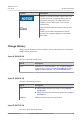
Symbol Conventions
The symbols that may be found in this document are defined as follows.
Symbol
Description
Indicates an imminently hazardous situation which, if
not avoided, will result in death or serious injury.
Indicates a potentially hazardous situation which, if not
avoided, could result in death or serious injury.
Indicates a potentially hazardous situation which, if not
avoided, may result in minor or moderate injury.
2288H V5 Server
User Guide
About This Document
Issue 04 (2018-09-04)
Copyright © Huawei Technologies Co., Ltd.
ii
About This Document
Purpose
This document describes the appearance, functions, structure, and parameters of the 2288H
V5, and how to install an OS, replace parts, and install, remove, configure, and troubleshoot
the server.
You can perform installation, removal, power-on, power-off, basic configuration, OS
installation, parts replacement, and troubleshooting of the 2288H V5 by referring to this
document.
Intended Audience
This document is intended for:
l
Huawei technical support engineers
l
Technical support engineers from channel partners
l
Enterprise administrators
Symbol Conventions
The symbols that may be found in this document are defined as follows.
Symbol
Description
Indicates an imminently hazardous situation which, if
not avoided, will result in death or serious injury.
Indicates a potentially hazardous situation which, if not
avoided, could result in death or serious injury.
Indicates a potentially hazardous situation which, if not
avoided, may result in minor or moderate injury.
2288H V5 Server
User Guide
About This Document
Issue 04 (2018-09-04)
Copyright © Huawei Technologies Co., Ltd.
ii
Symbol
Description
Indicates a potentially hazardous situation which, if not
avoided, could result in equipment damage, data loss,
performance deterioration, or unanticipated results.
NOTICE is used to address practices not related to
personal injury.
Calls attention to important information, best practices
and tips.
NOTE is used to address information not related to
personal injury, equipment damage, and environment
deterioration.
Change History
Changes between document issues are cumulative. The latest document issue contains all the
changes made in earlier issues.
Issue 04 (2018-09-04)
This issue is the fourth official release.
Mode
Description
New
Added the 8 x 2.5-inch SAS/SATA + 12 x 2.5-inch NVMe drive
configuration. For details, see7.7 Internal Cabling for a Server
with 8 x 2.5-inch SAS/SATA + 12 x 2.5-inch NVMe drives.
Issue 03 (2018-04-18)
This issue is the third official release.
Mode
Description
New
l Added TPM specifications. For details, see 13.1 Technical
Specifications.
l Added built-indrive specifications. For details, see 2.9.1 Drive
Slot Numbers.
Modified
Modified operating temperature specifications.
Issue 02 (2017-12-29)
This issue is the second official release.
2288H V5 Server
User Guide
About This Document
Issue 04 (2018-09-04)
Copyright © Huawei Technologies Co., Ltd.
iii
Symbol
Description
Indicates a potentially hazardous situation which, if not
avoided, could result in equipment damage, data loss,
performance deterioration, or unanticipated results.
NOTICE is used to address practices not related to
personal injury.
Calls attention to important information, best practices
and tips.
NOTE is used to address information not related to
personal injury, equipment damage, and environment
deterioration.
Change History
Changes between document issues are cumulative. The latest document issue contains all the
changes made in earlier issues.
Issue 04 (2018-09-04)
This issue is the fourth official release.
Mode
Description
New
Added the 8 x 2.5-inch SAS/SATA + 12 x 2.5-inch NVMe drive
configuration. For details, see7.7 Internal Cabling for a Server
with 8 x 2.5-inch SAS/SATA + 12 x 2.5-inch NVMe drives.
Issue 03 (2018-04-18)
This issue is the third official release.
Mode
Description
New
l Added TPM specifications. For details, see 13.1 Technical
Specifications.
l Added built-indrive specifications. For details, see 2.9.1 Drive
Slot Numbers.
Modified
Modified operating temperature specifications.
Issue 02 (2017-12-29)
This issue is the second official release.
2288H V5 Server
User Guide
About This Document
Issue 04 (2018-09-04)
Copyright © Huawei Technologies Co., Ltd.
iii
Mode
Description
New
Added NVMe SSD configurations. For details, see 2.9.1 Drive
Slot Numbers.
Issue 01 (2017-08-13)
This issue is the first official release.
2288H V5 Server
User Guide
About This Document
Issue 04 (2018-09-04)
Copyright © Huawei Technologies Co., Ltd.
iv
Mode
Description
New
Added NVMe SSD configurations. For details, see 2.9.1 Drive
Slot Numbers.
Issue 01 (2017-08-13)
This issue is the first official release.
2288H V5 Server
User Guide
About This Document
Issue 04 (2018-09-04)
Copyright © Huawei Technologies Co., Ltd.
iv
Contents
About This Document.....................................................................................................................ii
1 Overview......................................................................................................................................... 1
2 Components....................................................................................................................................2
2.1 Front Panel Components................................................................................................................................................ 2
2.2 Front Panel Indicators and Buttons................................................................................................................................ 5
2.3 Rear Panel Components..................................................................................................................................................9
2.4 Rear Panel Indicators....................................................................................................................................................12
2.5 Flexible NIC................................................................................................................................................................. 13
2.6 Mainboard Components............................................................................................................................................... 16
2.7 Drive Backplane Connectors........................................................................................................................................18
2.8 DIMM Slot Locations...................................................................................................................................................22
2.9 Drive Slot Numbers and Indicators.............................................................................................................................. 23
2.9.1 Drive Slot Numbers...................................................................................................................................................23
2.9.2 SAS/SATA Drive Indicators......................................................................................................................................30
2.9.3 NVMe SSD Indicators...............................................................................................................................................31
2.10 Riser Cards and PCIe Slots.........................................................................................................................................32
2.11 Fan Modules............................................................................................................................................................... 37
2.12 Physical Structure.......................................................................................................................................................38
3 Basic Operations.......................................................................................................................... 40
3.1 Powering On the Server................................................................................................................................................40
3.2 Powering Off the Server............................................................................................................................................... 41
3.3 Removing the Server and Guide Rails......................................................................................................................... 42
3.3.1 Removing the Server and L-Shaped Guide Rails......................................................................................................42
3.3.2 Removing the Server and Adjustable Guide Rails.................................................................................................... 44
3.3.3 Removing the Server and Holding Rails................................................................................................................... 46
3.4 Removing the Chassis Cover........................................................................................................................................50
3.5 Installing the Chassis Cover......................................................................................................................................... 51
3.6 Removing a Fan Module.............................................................................................................................................. 51
3.7 Removing Cables from a PSU......................................................................................................................................52
3.8 Removing the Air Duct.................................................................................................................................................55
3.9 Installing the Air Duct.................................................................................................................................................. 57
3.10 Removing the Built-in Drive Assembly..................................................................................................................... 58
2288H V5 Server
User Guide
Contents
Issue 04 (2018-09-04)
Copyright © Huawei Technologies Co., Ltd.
v
Contents
About This Document.....................................................................................................................ii
1 Overview......................................................................................................................................... 1
2 Components....................................................................................................................................2
2.1 Front Panel Components................................................................................................................................................ 2
2.2 Front Panel Indicators and Buttons................................................................................................................................ 5
2.3 Rear Panel Components..................................................................................................................................................9
2.4 Rear Panel Indicators....................................................................................................................................................12
2.5 Flexible NIC................................................................................................................................................................. 13
2.6 Mainboard Components............................................................................................................................................... 16
2.7 Drive Backplane Connectors........................................................................................................................................18
2.8 DIMM Slot Locations...................................................................................................................................................22
2.9 Drive Slot Numbers and Indicators.............................................................................................................................. 23
2.9.1 Drive Slot Numbers...................................................................................................................................................23
2.9.2 SAS/SATA Drive Indicators......................................................................................................................................30
2.9.3 NVMe SSD Indicators...............................................................................................................................................31
2.10 Riser Cards and PCIe Slots.........................................................................................................................................32
2.11 Fan Modules............................................................................................................................................................... 37
2.12 Physical Structure.......................................................................................................................................................38
3 Basic Operations.......................................................................................................................... 40
3.1 Powering On the Server................................................................................................................................................40
3.2 Powering Off the Server............................................................................................................................................... 41
3.3 Removing the Server and Guide Rails......................................................................................................................... 42
3.3.1 Removing the Server and L-Shaped Guide Rails......................................................................................................42
3.3.2 Removing the Server and Adjustable Guide Rails.................................................................................................... 44
3.3.3 Removing the Server and Holding Rails................................................................................................................... 46
3.4 Removing the Chassis Cover........................................................................................................................................50
3.5 Installing the Chassis Cover......................................................................................................................................... 51
3.6 Removing a Fan Module.............................................................................................................................................. 51
3.7 Removing Cables from a PSU......................................................................................................................................52
3.8 Removing the Air Duct.................................................................................................................................................55
3.9 Installing the Air Duct.................................................................................................................................................. 57
3.10 Removing the Built-in Drive Assembly..................................................................................................................... 58
2288H V5 Server
User Guide
Contents
Issue 04 (2018-09-04)
Copyright © Huawei Technologies Co., Ltd.
v
3.11 Installing the Built-in Drive Assembly.......................................................................................................................59
3.12 Removing a Riser Card Tray...................................................................................................................................... 60
3.13 Installing a Riser Card Tray........................................................................................................................................64
4 Setup.............................................................................................................................................. 67
4.1 Environmental Requirements....................................................................................................................................... 67
4.1.1 Space and Airflow Requirements..............................................................................................................................67
4.1.2 Temperature and Humidity Requirements.................................................................................................................68
4.1.3 Cabinet Requirements................................................................................................................................................68
4.2 Unpacking the Chassis..................................................................................................................................................69
4.3 Installing Optional Parts............................................................................................................................................... 69
4.4 Installing the Server on Guide Rails.............................................................................................................................69
4.4.1 Installing with L-Shaped Guide Rails....................................................................................................................... 69
4.4.2 Installing with Adjustable Guide Rails......................................................................................................................72
4.4.3 Installing with Holding Rails.....................................................................................................................................74
4.5 Connecting External Cables......................................................................................................................................... 79
4.5.1 Cabling Overview......................................................................................................................................................80
4.5.2 Connecting Cables to a Mouse, Keyboard, and VGA Port....................................................................................... 81
4.5.3 Connecting a Network Cable.....................................................................................................................................81
4.5.4 Connecting a Cable to a 10GE Optical Port..............................................................................................................83
4.5.5 Connecting a 56G IB Cable.......................................................................................................................................86
4.5.6 Connecting a USB Device.........................................................................................................................................88
4.5.7 Connecting a Serial Cable......................................................................................................................................... 88
4.5.8 Connecting Cables to a PSU......................................................................................................................................89
4.5.9 Verifying Cable Connections.....................................................................................................................................92
4.6 Initial Configuration..................................................................................................................................................... 92
4.6.1 Default Data...............................................................................................................................................................93
4.6.2 Configuration Process................................................................................................................................................93
4.6.3 Setting the Management Network Port IP Address...................................................................................................95
4.6.4 Logging In to the iBMC WebUI................................................................................................................................98
4.6.5 Checking the Server...................................................................................................................................................99
4.6.6 Changing Initial Passwords..................................................................................................................................... 102
4.6.7 Configuring RAID...................................................................................................................................................105
4.6.8 Configuring the BIOS..............................................................................................................................................105
4.6.9 Installing an OS........................................................................................................................................................111
5 Optional Part Installation........................................................................................................ 112
5.1 Precautions..................................................................................................................................................................113
5.2 Front Bezel (Optional)................................................................................................................................................113
5.2.1 Removing the Front Bezel.......................................................................................................................................113
5.2.2 Installing the Front Bezel.........................................................................................................................................114
5.3 Drive........................................................................................................................................................................... 116
5.3.1 Removing a SAS/SATA Drive.................................................................................................................................116
5.3.2 Installing a SAS/SATA Drive.................................................................................................................................. 118
2288H V5 Server
User Guide
Contents
Issue 04 (2018-09-04)
Copyright © Huawei Technologies Co., Ltd.
vi
3.11 Installing the Built-in Drive Assembly.......................................................................................................................59
3.12 Removing a Riser Card Tray...................................................................................................................................... 60
3.13 Installing a Riser Card Tray........................................................................................................................................64
4 Setup.............................................................................................................................................. 67
4.1 Environmental Requirements....................................................................................................................................... 67
4.1.1 Space and Airflow Requirements..............................................................................................................................67
4.1.2 Temperature and Humidity Requirements.................................................................................................................68
4.1.3 Cabinet Requirements................................................................................................................................................68
4.2 Unpacking the Chassis..................................................................................................................................................69
4.3 Installing Optional Parts............................................................................................................................................... 69
4.4 Installing the Server on Guide Rails.............................................................................................................................69
4.4.1 Installing with L-Shaped Guide Rails....................................................................................................................... 69
4.4.2 Installing with Adjustable Guide Rails......................................................................................................................72
4.4.3 Installing with Holding Rails.....................................................................................................................................74
4.5 Connecting External Cables......................................................................................................................................... 79
4.5.1 Cabling Overview......................................................................................................................................................80
4.5.2 Connecting Cables to a Mouse, Keyboard, and VGA Port....................................................................................... 81
4.5.3 Connecting a Network Cable.....................................................................................................................................81
4.5.4 Connecting a Cable to a 10GE Optical Port..............................................................................................................83
4.5.5 Connecting a 56G IB Cable.......................................................................................................................................86
4.5.6 Connecting a USB Device.........................................................................................................................................88
4.5.7 Connecting a Serial Cable......................................................................................................................................... 88
4.5.8 Connecting Cables to a PSU......................................................................................................................................89
4.5.9 Verifying Cable Connections.....................................................................................................................................92
4.6 Initial Configuration..................................................................................................................................................... 92
4.6.1 Default Data...............................................................................................................................................................93
4.6.2 Configuration Process................................................................................................................................................93
4.6.3 Setting the Management Network Port IP Address...................................................................................................95
4.6.4 Logging In to the iBMC WebUI................................................................................................................................98
4.6.5 Checking the Server...................................................................................................................................................99
4.6.6 Changing Initial Passwords..................................................................................................................................... 102
4.6.7 Configuring RAID...................................................................................................................................................105
4.6.8 Configuring the BIOS..............................................................................................................................................105
4.6.9 Installing an OS........................................................................................................................................................111
5 Optional Part Installation........................................................................................................ 112
5.1 Precautions..................................................................................................................................................................113
5.2 Front Bezel (Optional)................................................................................................................................................113
5.2.1 Removing the Front Bezel.......................................................................................................................................113
5.2.2 Installing the Front Bezel.........................................................................................................................................114
5.3 Drive........................................................................................................................................................................... 116
5.3.1 Removing a SAS/SATA Drive.................................................................................................................................116
5.3.2 Installing a SAS/SATA Drive.................................................................................................................................. 118
2288H V5 Server
User Guide
Contents
Issue 04 (2018-09-04)
Copyright © Huawei Technologies Co., Ltd.
vi
5.3.3 Removing an NVMe SSD....................................................................................................................................... 120
5.3.4 Installing an NVMe SSD.........................................................................................................................................126
5.4 PSU.............................................................................................................................................................................127
5.4.1 AC PSU................................................................................................................................................................... 127
5.4.2 DC PSU................................................................................................................................................................... 130
5.5 PCIe Card on a Riser Card......................................................................................................................................... 132
5.6 DVD Drive................................................................................................................................................................. 135
5.7 Built-in USB Flash Drive........................................................................................................................................... 138
5.8 Screw-in RAID Controller Card.................................................................................................................................140
5.9 Avago SAS3004iMR RAID Controller Card............................................................................................................. 141
5.10 M.2 SSD Module......................................................................................................................................................142
5.11 Supercapacitor.......................................................................................................................................................... 143
5.12 CPU.......................................................................................................................................................................... 148
5.13 DIMM.......................................................................................................................................................................155
5.13.1 DIMM Compatibility Information.........................................................................................................................155
5.13.2 Memory Subsystem Architecture.......................................................................................................................... 156
5.13.3 DIMM Ranks.........................................................................................................................................................159
5.13.4 DIMM Identification............................................................................................................................................. 160
5.13.5 Memory Protection................................................................................................................................................161
5.13.6 DIMM Installation Rules.......................................................................................................................................161
5.13.7 Installing a DIMM.................................................................................................................................................162
5.14 TPM/TCM................................................................................................................................................................ 163
5.14.1 Installing a TPM/TCM.......................................................................................................................................... 164
5.14.2 Enabling the TPM/TCM........................................................................................................................................165
5.15 Flexible NIC............................................................................................................................................................. 166
5.16 Rear Drive Module................................................................................................................................................... 169
5.17 Left Mounting Ear.................................................................................................................................................... 171
5.18 Right Mounting Ear..................................................................................................................................................172
6 Software and Hardware Compatibility.................................................................................174
7 Internal Cabling.........................................................................................................................175
7.1 Internal Cabling for a Server with 8 x 2.5-inch Drives.............................................................................................. 176
7.2 Internal Cabling for a Server with 12 x 3.5-inch Expander Drives (1)...................................................................... 183
7.3 Internal Cabling for a Server with 12 x 3.5-inch Expander Drives (2)...................................................................... 191
7.4 Internal Cabling for a Server with 12 x 3.5-inch Pass-Through Drives (1)............................................................... 195
7.5 Internal Cabling for a Server with 12 x 3.5-inch Pass-Through Drives (2)............................................................... 200
7.6 Internal Cabling for a Server with 12 x 3.5-inch Pass-Through Drives (3)............................................................... 203
7.7 Internal Cabling for a Server with 8 x 2.5-inch SAS/SATA + 12 x 2.5-inch NVMe drives...................................... 207
7.8 Internal Cabling for a Server with 24 x 2.5-inch Front Drives...................................................................................212
7.9 Internal Cabling for a Server with 24 x 2.5-inch NVMe SSDs..................................................................................216
7.10 Internal Cabling for a Server with 25 x 2.5-inch Front Drives (1)...........................................................................221
7.11 Internal Cabling for a Server with 25 x 2.5-inch Front Drives (2)...........................................................................226
7.12 Internal Cabling for the Riser Card in I/O Module 3............................................................................................... 230
2288H V5 Server
User Guide
Contents
Issue 04 (2018-09-04)
Copyright © Huawei Technologies Co., Ltd.
vii
5.3.3 Removing an NVMe SSD....................................................................................................................................... 120
5.3.4 Installing an NVMe SSD.........................................................................................................................................126
5.4 PSU.............................................................................................................................................................................127
5.4.1 AC PSU................................................................................................................................................................... 127
5.4.2 DC PSU................................................................................................................................................................... 130
5.5 PCIe Card on a Riser Card......................................................................................................................................... 132
5.6 DVD Drive................................................................................................................................................................. 135
5.7 Built-in USB Flash Drive........................................................................................................................................... 138
5.8 Screw-in RAID Controller Card.................................................................................................................................140
5.9 Avago SAS3004iMR RAID Controller Card............................................................................................................. 141
5.10 M.2 SSD Module......................................................................................................................................................142
5.11 Supercapacitor.......................................................................................................................................................... 143
5.12 CPU.......................................................................................................................................................................... 148
5.13 DIMM.......................................................................................................................................................................155
5.13.1 DIMM Compatibility Information.........................................................................................................................155
5.13.2 Memory Subsystem Architecture.......................................................................................................................... 156
5.13.3 DIMM Ranks.........................................................................................................................................................159
5.13.4 DIMM Identification............................................................................................................................................. 160
5.13.5 Memory Protection................................................................................................................................................161
5.13.6 DIMM Installation Rules.......................................................................................................................................161
5.13.7 Installing a DIMM.................................................................................................................................................162
5.14 TPM/TCM................................................................................................................................................................ 163
5.14.1 Installing a TPM/TCM.......................................................................................................................................... 164
5.14.2 Enabling the TPM/TCM........................................................................................................................................165
5.15 Flexible NIC............................................................................................................................................................. 166
5.16 Rear Drive Module................................................................................................................................................... 169
5.17 Left Mounting Ear.................................................................................................................................................... 171
5.18 Right Mounting Ear..................................................................................................................................................172
6 Software and Hardware Compatibility.................................................................................174
7 Internal Cabling.........................................................................................................................175
7.1 Internal Cabling for a Server with 8 x 2.5-inch Drives.............................................................................................. 176
7.2 Internal Cabling for a Server with 12 x 3.5-inch Expander Drives (1)...................................................................... 183
7.3 Internal Cabling for a Server with 12 x 3.5-inch Expander Drives (2)...................................................................... 191
7.4 Internal Cabling for a Server with 12 x 3.5-inch Pass-Through Drives (1)............................................................... 195
7.5 Internal Cabling for a Server with 12 x 3.5-inch Pass-Through Drives (2)............................................................... 200
7.6 Internal Cabling for a Server with 12 x 3.5-inch Pass-Through Drives (3)............................................................... 203
7.7 Internal Cabling for a Server with 8 x 2.5-inch SAS/SATA + 12 x 2.5-inch NVMe drives...................................... 207
7.8 Internal Cabling for a Server with 24 x 2.5-inch Front Drives...................................................................................212
7.9 Internal Cabling for a Server with 24 x 2.5-inch NVMe SSDs..................................................................................216
7.10 Internal Cabling for a Server with 25 x 2.5-inch Front Drives (1)...........................................................................221
7.11 Internal Cabling for a Server with 25 x 2.5-inch Front Drives (2)...........................................................................226
7.12 Internal Cabling for the Riser Card in I/O Module 3............................................................................................... 230
2288H V5 Server
User Guide
Contents
Issue 04 (2018-09-04)
Copyright © Huawei Technologies Co., Ltd.
vii
8 Software and Configuration Utilities....................................................................................235
8.1 BIOS........................................................................................................................................................................... 235
8.2 iBMC.......................................................................................................................................................................... 236
8.3 Upgrading the System................................................................................................................................................ 237
8.4 FusionServer Tools uMate..........................................................................................................................................238
8.5 FusionServer Tools Toolkit.........................................................................................................................................239
9 Troubleshooting........................................................................................................................ 240
10 Battery........................................................................................................................................241
10.1 Removing the Battery...............................................................................................................................................241
10.2 Installing the Battery................................................................................................................................................ 242
11 Warranty and Safety................................................................................................................244
11.1 Warranty....................................................................................................................................................................244
11.2 Safety........................................................................................................................................................................ 244
12 Preventing Electrostatic Discharge...................................................................................... 245
12.1 Operation Instructions.............................................................................................................................................. 245
12.2 ESD Wrist Strap........................................................................................................................................................246
13 Product Specifications............................................................................................................ 247
13.1 Technical Specifications........................................................................................................................................... 247
13.2 Physical and Environmental Specifications............................................................................................................. 251
13.3 PSU Specifications................................................................................................................................................... 256
14 Common Operations...............................................................................................................257
14.1 Querying the Management Network Port IP Address..............................................................................................257
14.2 Logging In to the Remote Virtual Console...............................................................................................................260
14.3 Logging In to the iBMC CLI....................................................................................................................................262
14.4 Logging In to the Server Using the IRC...................................................................................................................264
14.5 Logging In to the Server over a Serial Port Using PuTTY...................................................................................... 271
14.6 Logging In to the Server over a Network Port Using PuTTY..................................................................................272
15 Support and Other Resources............................................................................................... 275
15.1 Technical Support..................................................................................................................................................... 275
15.2 Product Information Resources................................................................................................................................ 276
15.3 Maintenance Tools....................................................................................................................................................276
A Appendix....................................................................................................................................278
A.1 Logical Structure....................................................................................................................................................... 278
A.2 RAS Features.............................................................................................................................................................279
A.3 Glossary..................................................................................................................................................................... 280
A.4 Acronyms and Abbreviations.................................................................................................................................... 282
2288H V5 Server
User Guide
Contents
Issue 04 (2018-09-04)
Copyright © Huawei Technologies Co., Ltd.
viii
8 Software and Configuration Utilities....................................................................................235
8.1 BIOS........................................................................................................................................................................... 235
8.2 iBMC.......................................................................................................................................................................... 236
8.3 Upgrading the System................................................................................................................................................ 237
8.4 FusionServer Tools uMate..........................................................................................................................................238
8.5 FusionServer Tools Toolkit.........................................................................................................................................239
9 Troubleshooting........................................................................................................................ 240
10 Battery........................................................................................................................................241
10.1 Removing the Battery...............................................................................................................................................241
10.2 Installing the Battery................................................................................................................................................ 242
11 Warranty and Safety................................................................................................................244
11.1 Warranty....................................................................................................................................................................244
11.2 Safety........................................................................................................................................................................ 244
12 Preventing Electrostatic Discharge...................................................................................... 245
12.1 Operation Instructions.............................................................................................................................................. 245
12.2 ESD Wrist Strap........................................................................................................................................................246
13 Product Specifications............................................................................................................ 247
13.1 Technical Specifications........................................................................................................................................... 247
13.2 Physical and Environmental Specifications............................................................................................................. 251
13.3 PSU Specifications................................................................................................................................................... 256
14 Common Operations...............................................................................................................257
14.1 Querying the Management Network Port IP Address..............................................................................................257
14.2 Logging In to the Remote Virtual Console...............................................................................................................260
14.3 Logging In to the iBMC CLI....................................................................................................................................262
14.4 Logging In to the Server Using the IRC...................................................................................................................264
14.5 Logging In to the Server over a Serial Port Using PuTTY...................................................................................... 271
14.6 Logging In to the Server over a Network Port Using PuTTY..................................................................................272
15 Support and Other Resources............................................................................................... 275
15.1 Technical Support..................................................................................................................................................... 275
15.2 Product Information Resources................................................................................................................................ 276
15.3 Maintenance Tools....................................................................................................................................................276
A Appendix....................................................................................................................................278
A.1 Logical Structure....................................................................................................................................................... 278
A.2 RAS Features.............................................................................................................................................................279
A.3 Glossary..................................................................................................................................................................... 280
A.4 Acronyms and Abbreviations.................................................................................................................................... 282
2288H V5 Server
User Guide
Contents
Issue 04 (2018-09-04)
Copyright © Huawei Technologies Co., Ltd.
viii
1 Overview
The Huawei FusionServer 2288H V5 (marked H22H-05 on the nameplate) is a 2U 2-socket
rack server developed for Internet, Internet data center (IDC), cloud computing, enterprise,
and telecom service applications.
The 2288H V5 is ideal for IT core services, cloud computing virtualization, high-performance
computing, distributed storage, big data processing, enterprise or telecom service applications,
and other complex workloads. It combines low power consumption with high scalability and
reliability, and easy deployment and management.
Figure 1-1 shows the appearance of a server with 12 drives.
Figure 1-1 Appearance
2288H V5 Server
User Guide
1 Overview
Issue 04 (2018-09-04)
Copyright © Huawei Technologies Co., Ltd.
1
1 Overview
The Huawei FusionServer 2288H V5 (marked H22H-05 on the nameplate) is a 2U 2-socket
rack server developed for Internet, Internet data center (IDC), cloud computing, enterprise,
and telecom service applications.
The 2288H V5 is ideal for IT core services, cloud computing virtualization, high-performance
computing, distributed storage, big data processing, enterprise or telecom service applications,
and other complex workloads. It combines low power consumption with high scalability and
reliability, and easy deployment and management.
Figure 1-1 shows the appearance of a server with 12 drives.
Figure 1-1 Appearance
2288H V5 Server
User Guide
1 Overview
Issue 04 (2018-09-04)
Copyright © Huawei Technologies Co., Ltd.
1
2 Components
2.1 Front Panel Components
2.2 Front Panel Indicators and Buttons
2.3 Rear Panel Components
2.4 Rear Panel Indicators
2.5 Flexible NIC
2.6 Mainboard Components
2.7 Drive Backplane Connectors
2.8 DIMM Slot Locations
2.9 Drive Slot Numbers and Indicators
2.10 Riser Cards and PCIe Slots
2.11 Fan Modules
2.12 Physical Structure
2.1 Front Panel Components
l
Figure 2-1 shows the components on the front panel of a server with eight 2.5-inch
drives.
2288H V5 Server
User Guide
2 Components
Issue 04 (2018-09-04)
Copyright © Huawei Technologies Co., Ltd.
2
Figure 2-1 Components on the front panel of a server with eight 2.5-inch drives
1
USB 2.0 ports
2
Built-in DVD drive (optional)
3
USB 3.0 port
4
VGA port
5
Label plate with an SN label
6
Drive
l
Figure 2-2 shows the components on the front panel of a server with twelve 3.5-inch
front drives.
Figure 2-2 Components on the front panel of a server with twelve 3.5-inch front drives
1
USB 2.0 ports
2
Label plate with an SN label
3
Drive
-
-
l
Figure 2-3 shows the components on the front panel of a server with 8 x 2.5-inch SAS/
SATA + 12 x 2.5-inch NVMe drives.
Figure 2-3 Components on the front panel of a server with 8 x 2.5-inch SAS/SATA + 12
x 2.5-inch NVMe drives
1
USB 2.0 ports
2
Drive
3
Filler module
4
Label plate with an SN label
l
Figure 2-4 shows the components on the front panel of a server with twenty-four 2.5-
inch front drives.
2288H V5 Server
User Guide
2 Components
Issue 04 (2018-09-04)
Copyright © Huawei Technologies Co., Ltd.
3
Figure 2-4 Components on the front panel of a server with twenty-four 2.5-inch front
drives
1
USB 2.0 ports
2
USB 3.0 port
3
VGA port
4
Label plate with an SN label
5
Drive
-
-
l
Figure 2-5 shows the components on the front panel of a server with twenty-five 2.5-
inch front drives.
Figure 2-5 Components on the front panel of a server with twenty-five 2.5-inch front
drives
1
USB 2.0 ports
2
Label plate with an SN label
3
Drive
-
-
Table 2-1 Ports on the front panel
Port
Type
Description
VGA port
DB15
The VGA port is connected to a
terminal, such as a monitor or
KVM.
USB port
USB 2.0/USB 3.0
The USB ports allow USB
devices to be connected to the
server.
NOTE
Before connecting an external USB
device, check that the USB device
functions properly. A server may
operate abnormally if an abnormal
USB device is connected.
2288H V5 Server
User Guide
2 Components
Issue 04 (2018-09-04)
Copyright © Huawei Technologies Co., Ltd.
4
SN
The serial number (SN) on the label is a string that uniquely identifies a server. The SN is
required when you contact Huawei technical support.
Figure 2-6 shows the SN format.
Figure 2-6 SN example
Table 2-2 SN description
No.
Description
1
SN ID (two characters), which is 21.
2
Material identification code (eight characters), that is, processing code.
3
Vendor code (two characters). The value 10 indicates Huawei and other
values indicate outsourcing vendors.
4
Year and month (two characters).
l The first character indicates the year. Digits 1 to 9 indicate 2001 to
2009, letters A to H indicate 2010 to 2017, letters J to N indicate 2018
to 2022, and letters P to Y indicate 2023 to 2032.
NOTE
The years from 2010 are represented by upper-case letters excluding I, O, and
Z because the three letters are similar to digits 1, 0, and 2.
l The second character indicates the month. Digits 1 to 9 indicate
January to September, and letters A to C indicate October to
December.
5
Serial number (six characters).
6
RoHS compliance (one character). Y indicates environment-friendly
processing.
7
Internal model, that is, product name.
2.2 Front Panel Indicators and Buttons
l
Figure 2-7 shows the indicators and buttons on the front panel of a server with eight 2.5-
inch drives.
2288H V5 Server
User Guide
2 Components
Issue 04 (2018-09-04)
Copyright © Huawei Technologies Co., Ltd.
5
Figure 2-7 Indicators and buttons on the front panel of a server with eight 2.5-inch
drives
1 LOM port connection status indicators (1 to 4 from top to down)
2 NMI button
3 Fault diagnostic LED
4 Health indicator
5 UID button/indicator
6 Power button/indicator
l
Figure 2-8 shows the indicators and buttons on the front panel of a server with twelve
3.5-inch front drives.
Figure 2-8 Indicators and buttons on the front panel of a server with twelve 3.5-inch
front drives
1 LOM port connection status indicators (1 to 4 from top to down)
2 Fault diagnostic LED
3 Health indicator
4 UID button/indicator
5 Power button/indicator
- -
l
Figure 2-9 shows the indicators and buttons on the front panel of a server with 8 x 2.5-
inch SAS/SATA + 12 x 2.5-inch NVMe drives.
Figure 2-9 Indicators and buttons on the front panel of a server with 8 x 2.5-inch SAS/
SATA + 12 x 2.5-inch NVMe drives
1 LOM port connection status indicators (1 to 4 from top to down)
2 Fault diagnostic LED
3 Health indicator
4 UID button/indicator
5 Power button/indicator
- -
l
Figure 2-10 shows the indicators and buttons on the front panel of a server with twenty-
four 2.5-inch front drives.
2288H V5 Server
User Guide
2 Components
Issue 04 (2018-09-04)
Copyright © Huawei Technologies Co., Ltd.
6
Figure 2-10 Indicators and buttons on the front panel of a server with twenty-four 2.5-
inch front drives
1 LOM port connection status indicators (1 to 4 from top to down)
2 Fault diagnostic LED
3 Health indicator
4 UID button/indicator
5 Power button/indicator
6 NMI button
l
Figure 2-11 shows the indicators and buttons on the front panel of a server with twenty-
five 2.5-inch front drives.
Figure 2-11 Indicators and buttons on the front panel of a server with twenty-five 2.5-
inch front drives
1 LOM port connection status indicators (1 to 4 from top to down)
2 Fault diagnostic LED
3 Health indicator
4 UID button/indicator
5 Power button/indicator
- -
Table 2-3 Indicators and buttons on the front panel
Silkscr
een
Indicator/
Button
State Description
Fault
diagnostic
LED
l ---: The server is operating normally.
l Error code: A server component is faulty.
For details about error codes, see the Huawei Rack Server
iBMC Alarm Handling.
2288H V5 Server
User Guide
2 Components
Issue 04 (2018-09-04)
Copyright © Huawei Technologies Co., Ltd.
7
Silkscr
een
Indicator/
Button
State Description
Power
button/
indicator
Power indicator
l Steady yellow: The server is ready to power on.
l Steady green: The server is properly powered on.
l Blinking yellow: The iBMC is starting.
l Off: The server is not connected to a power source.
Power button
l When the server is powered on, you can press this button to
shut down the OS.
l When the server is powered on, you can hold down this
button for 6 seconds to force the server to power off.
l When the server is ready to power on, you can press this
button to start the server.
UID button/
indicator
The UID button/indicator helps identify and locate a server. You
can turn on or off the UID indicator by pressing the UID button
or remotely using the iBMC
UID indicator
l Steady blue/Blinking blue: The server is being located.
l Off: The server is not being located.
UID button
l You can press this button to turn on or off the UID indicator.
l You can press and hold down this button for 4 to 6 seconds to
reset the iBMC.
Health
indicator
l Steady green: The server is operating properly.
l Blinking red at 1 Hz: A major alarm has been generated on
the server.
l Blinking red at 5 Hz: A critical alarm has been generated on
the server.
NMI button
The NMI button triggers a server to generate a non-maskable
interrupt. You can press this button or control it remotely on the
iBMC WebUI.
NOTE
l
Use the NMI button only when the OS is abnormal. Do not use this
button when the server is operating properly.
l
Before using the NMI button, ensure that the OS has the NMI
processing program. Otherwise, the OS may crash. Exercise caution
when using this button.
2288H V5 Server
User Guide
2 Components
Issue 04 (2018-09-04)
Copyright © Huawei Technologies Co., Ltd.
8
Silkscr
een
Indicator/
Button
State Description
LOM port
connection
status
indicator
Each indicator shows the status of an Ethernet port on the LOM.
l Steady green: The network port is properly connected.
l Off: The network port is not in use or has failed.
NOTE
l
The indicators correspond to the two 10GE and two GE LOM ports.
l
The LOM has a standby power supply and is not powered off after the
service system is powered off. If the network ports are properly
connected to other working network devices, the network ports are
still connected and the indicators are on.
2.3 Rear Panel Components
The 2288H V5 has two types of mainboards. One mainboard provides two 10GE and two GE
electrical ports. Figure1 Rear panel components 1 shows its rear panel components. The
other motherboard provides two 10GE optical ports and two GE electrical ports. Figure2
Rear panel components 2 shows its rear panel components.
Figure 2-12 Rear panel components 1
1
I/O module 1
2
I/O module 2
3
I/O module 3
4
Power supply unit (PSU) 2
5
PSU sockets
6
PSU 1
7
Flexible NIC (optional)
8
USB 3.0 ports
9
Serial port
10
Management network port
11
GE electrical ports
12
VGA port
13
10GE electrical ports
-
-
2288H V5 Server
User Guide
2 Components
Issue 04 (2018-09-04)
Copyright © Huawei Technologies Co., Ltd.
9
Figure 2-13 Rear panel components 2
1
I/O module 1
2
I/O module 2
3
I/O module 3
4
Power supply unit (PSU) 2
5
PSU sockets
6
PSU 1
7
Flexible NIC (optional)
8
USB 3.0 ports
9
Serial port
10
Management network port
11
GE electrical ports
12
VGA port
13
10GE optical ports
-
-
NOTE
I/O module 1, 2, and 3 can be rear drive modules or riser card modules. The preceding figure is for
reference only.
Table 2-4 Ports on the rear panel
Port
Type
Quantit
y
Description
10GE
electrical port
10GBASE-T
2
The 2288H V5 has two types of
mainboards. One mainboard provides two
10GE and two GE electrical ports. The
other motherboard provides two 10GE
optical ports and two GE electrical ports.
You can select either of them as required.
NOTE
10GE electrical ports or optical ports are
integrated service network ports on the server
mainboard.
10GE optical
port
10GE SFP+
2
VGA port
DB15
1
The VGA port is connected to a terminal,
such as a monitor or KVM.
GE electrical
port
1000BASE-T
2
Service network port integrated on the
server mainboard.
Serial port
RJ45
1
The serial port is used as the system serial
port by default. You can set it as the iBMC
serial port by using the iBMC CLI. This
port is used for debugging.
2288H V5 Server
User Guide
2 Components
Issue 04 (2018-09-04)
Copyright © Huawei Technologies Co., Ltd.
10
Port
Type
Quantit
y
Description
Management
network port
1000BASE-T
1
The 1000 Mbit/s Ethernet port is used for
server management.
USB port
USB 3.0
2
The USB ports allow USB devices to be
connected to the server.
NOTE
Before connecting an external USB device,
check that the USB device functions properly. A
server may operate abnormally if an abnormal
USB device is connected.
PSU socket
-
2
Determine the number of PSUs based on
actual requirements, but ensure that the
rated power of the PSUs is greater than that
of the server. When one PSU is used,
Predicted PSU Status cannot be set to
Active/Standby on the iBMC WebUI.
Table 2-5 LOM port description
LOM Port
Chip Model
Rate
Negotiation
Mode
Supported
Rate
Not
Supported
Rate
10GE optical
port
X722
Auto-
negotiation
10000 Mbit/s
(full duplex)
10000 Mbit/s
10/100/1000
Mbit/s
10GE electrical
port
Auto-
negotiation
1000 Mbit/s
(full duplex)
1000 Mbit/s
10/100 Mbit/s
Auto-
negotiation
10000 Mbit/s
(full duplex)
10000 Mbit/s
10/100 Mbit/s
GE electrical
port
Auto-
negotiation
1000 Mbit/s
(full duplex)
1000 Mbit/s
10/100 Mbit/s
NOTE
l
The LOM ports do not support forcible rates.
l
The GE LOM electrical port does not support SR-IOV.
2288H V5 Server
User Guide
2 Components
Issue 04 (2018-09-04)
Copyright © Huawei Technologies Co., Ltd.
11
2.4 Rear Panel Indicators
Figure 2-14 shows the indicators on the rear panel of the server.
Figure 2-14 Rear panel indicators
1 PSU indicator
2 UID indicator
3 Connection status indicator
4 Data transmission status indicator
5 Connection status indicator/Data transmission
status indicator
6 Transmission rate indicator
7 Transmission rate indicator
8 Connection status indicator/Data transmission status
indicator
Table 2-6 Indicators on the rear panel
Indicator
State Description
10GE
electrical
port
Transmission rate
indicator
l Steady green: The data transmission rate is
10 Gbit/s.
l Steady yellow: The data transmission rate is
1 Gbit/s.
l Off: The network port is not connected.
Connection status
indicator/Data
transmission status
indicator
l Steady green: The network port is properly
connected.
l Blinking green: Data is being transmitted.
l Off: The network port is not connected.
10GE
optical port
Connection status
indicator/Data
transmission status
indicator
l Steady green: The network port is properly
connected.
l Blinking green: Data is being transmitted.
l Off: The network port is not connected.
2288H V5 Server
User Guide
2 Components
Issue 04 (2018-09-04)
Copyright © Huawei Technologies Co., Ltd.
12
Indicator
State Description
Transmission rate
indicator
l Steady green: The data transmission rate is
10 Gbit/s.
l Steady yellow: The data transmission rate is
lower than 10 Gbit/s.
l Off: The network port is not connected.
GE
electrical
port
Connection status
indicator
l Steady green: The network port is properly
connected.
l Off: The network port is not connected.
Data transmission status
indicator
l Blinking yellow: Data is being transmitted.
l Off: No data is being transmitted.
UID indicator
The UID indicator helps identify and locate a
server. You can turn on or off the UID indicator
by pressing the UID button or remotely running
a command on the iBMC CLI.
l Steady blue/Blinking blue: The server is
being located.
l Off: The server is not being located.
PSU indicator
l Steady green: The power input and output
are normal.
l Steady orange: The input is normal, but no
power output is supplied due to overheat
protection, overcurrent protection, short
circuit protection, output overvoltage
protection, or some component failures.
l Blinking green at 1 Hz:
– The input is normal, the server is standby,
and the PSU is in MV6 mode. (The
output voltage is 6.7 V.)
– The input is overvoltage or undervoltage.
– The PSU is in deep hibernation mode.
l Blinking green at 4 Hz: under online
firmware upgrade.
l Off: No AC power is supplied.
2.5 Flexible NIC
Supported flexible NICs include:
l
SM211 (chip: i350) with two GE electrical ports
l
SM210 (chip: 5719)/SM212 (chip: i350) with four GE electrical ports
l
SM233 (chip: X540) with two 10GE electrical ports
2288H V5 Server
User Guide
2 Components
Issue 04 (2018-09-04)
Copyright © Huawei Technologies Co., Ltd.
13
l
SM252 (chip: CX3) with one 56G IB optical port
l
SM251 (chip: CX3) with two 56G IB optical ports
l
SM380 (chip: CX4) with two 25GE optical ports
Use the Huawei Server Compatibility Checker to obtain the latest model list.
The following figures show the indicators on these flexible NICs.
Figure 2-15 SM211 with two GE electrical ports
Figure 2-16 SM210/SM212 with four GE electrical ports
Figure 2-17 SM233 with two 10GE electrical ports
Figure 2-18 SM252 with one 56G IB optical port
Figure 2-19 SM251 with two 56G IB optical ports
2288H V5 Server
User Guide
2 Components
Issue 04 (2018-09-04)
Copyright © Huawei Technologies Co., Ltd.
14
Figure 2-20 SM380 with two 25GE optical ports
Table 2-7 Flexible NIC indicators
NIC Type
Indicator
State Description
l Flexible NIC with
two GE electrical
ports
l Flexible NIC with
four GE electrical
ports
Data transmission
status indicator
l Blinking yellow: Data is being
transmitted.
l Off: No data is being transmitted.
Connection status
indicator
l Steady green: The network port is
properly connected.
l Off: The network port is not
connected.
Flexible NIC with
two 10GE electrical
ports
Transmission rate
indicator
l Steady green: The data transmission
rate is 10 Gbit/s.
l Steady yellow: The data transmission
rate is 1 Gbit/s.
l Off: The data transmission rate is 10
Mbit/s or 100 Mbit/s.
Connection status
indicator/Data
transmission status
indicator
l Steady green: The network port is
properly connected.
l Blinking green: Data is being
transmitted.
l Off: No data is being transmitted or
the network port is not connected.
l Flexible NIC with
one 56G IB optical
port
l Flexible NIC with
two 56G IB
optical ports
Connection status
indicator
l Steady green: The physical link is
normal.
l Blinking green: The physical link is
abnormal.
l Off: No physical link is set up.
Data transmission
status indicator
l Steady yellow: The logical link is
normal but no data is being
transmitted.
l Blinking yellow: Data is being
transmitted.
l Off: No logical link is set up.
2288H V5 Server
User Guide
2 Components
Issue 04 (2018-09-04)
Copyright © Huawei Technologies Co., Ltd.
15
NIC Type
Indicator
State Description
Flexible NIC with
two 25GE optical
ports
Transmission rate
indicator
l Steady green: The data transmission
rate is 25 Gbit/s.
l Steady yellow: The data transmission
rate is 10 Gbit/s.
l Off: The network port is not
connected.
Connection status
indicator or data
transmission status
indicator
l Steady green: The network port is
properly connected.
l Blinking green: Data is being
transmitted.
l Off: The network port is not
connected.
2.6 Mainboard Components
Figure 2-21 shows the components on the mainboard.
2288H V5 Server
User Guide
2 Components
Issue 04 (2018-09-04)
Copyright © Huawei Technologies Co., Ltd.
16
Figure 2-21 Mainboard components
1
USB 3.0 port (USB 3.0 CONN/J169)
2
UID indicator (D6020)
3
Serial port
4
Management network port
5
GE electrical port
6
GE electrical port
7
VGA connector (VGA CONN/J112)
8
10GE optical port (10GE PORT2/J132) or 10GE
electrical port (10GE PORT2/J101)
NOTE
A 10GE optical port is available on a mainboard
that provides two 10GE optical ports and two GE
electrical ports. A 10GE electrical port is available
on a mainboard that provides two 10GE and two
GE electrical ports.
2288H V5 Server
User Guide
2 Components
Issue 04 (2018-09-04)
Copyright © Huawei Technologies Co., Ltd.
17
9
10GE optical port (10GE PORT1/J131) or
10GE electrical port (10GE PORT1/J100)
NOTE
A 10GE optical port is available on a
mainboard that provides two 10GE optical
ports and two GE electrical ports. A 10GE
electrical port is available on a mainboard
that provides two 10GE and two GE
electrical ports.
10 VROC key port (J130)
11 Riser card slot 1 (corresponding to CPU 1;
J108)
12 Rear drive backplane power connector 2 (REAR BP
PWR2/J126)
13 NC-SI connector (NCSI CONN/J99)
14 SATA signal connector 2 (SATA2/J71)
15 SATA signal connector 1 (SATA1/J67)
16 CPU 1 slimline connector (CPU1 SLIMELINE/J170)
17 Mini-SAS HD connector C (MINIHD PORT C/
J85)
18 Mini-SAS HD connector B (MINIHD PORT B/J84)
19 Mini-SAS HD connector A (MINIHD PORT A/
J86)
20 Rear drive backplane power connector 1 (REAR BP
PWR1/J127)
21 USB 3.0 port (FRONT USB3.0/J173)
22 Right mounting ear connector (RCIC/RCIF/RCIG
BOARD/J167)
23 TPM/TCM port (TPM CONN/J55)
24 LCD connector (LCD CONN/J87)
25 VGA connector (VGA BOARD/J160)
26 Fan 4 connector (2U FAN4/J148)
27 Fan 3 connector (2U FAN3/J145)
28 Fan 2 connector (2U FAN2/J146)
29 Fan 1 connector (1U/2U FAN1/J105)
30 Drive backplane connector (HDD BP CONN/J162)
31 Built-in drive power connector (INNER HDD
PWR/171)
32 Drive backplane power connector 1 (HDD BP
PWR2/J128)
33 Drive backplane power connector 2 (HDD BP
PWR2/J166)
34 Rear drive backplane power connector 3 (REAR BP
PWR3/J172)
35 Rear 4 x 2.5-inch drive backplane low-speed
signal connector (REAR 4*2.5 HDD BP/J164)
36 CPU 2 slimline A connector (CPU2 SLIMLINE A/
J140)
37 CPU 2 slimline B connector (CPU2 SLIMLINE
B/J139)
38 PSU 2 connector (J157)
39 PSU 1 connector (J156)
40 Built-in drive low-speed signal connector (INNER
HDD BP/J122)
41 Left mounting ear connector (LCIA BOARD/
J161)
42 Jumper (J176)
NOTE
COM_SW pins are used for changing the serial
port direction, and CLR_BMC_PW pins are used
for restoring the default iBMC settings.
43 I/O NIC connectors (IO BOARD/J159/J158)
44 RAID controller card connector (RAID CARD/J48)
45 Riser card slot 2 (CPU 2/J155)
-
-
2.7 Drive Backplane Connectors
Figure 2-22 shows the connectors on the drive backplane connecting eight 2.5-inch drives.
2288H V5 Server
User Guide
2 Components
Issue 04 (2018-09-04)
Copyright © Huawei Technologies Co., Ltd.
18
Figure 2-22 Backplane connecting eight 2.5-inch drives (BOM 03022HXW)
1 Front VGA connector (J26)
2 Backplane signal cable connector (J1)
3 DVD drive power connector (J11)
4 Mini-SAS HD connector (PORT B/J29)
5 Mini-SAS HD connector (PORT A/J28)
6 Power connector (J24)
Figure 2-23 shows the connectors on the expander backplane connecting twelve 3.5-inch
drives.
Figure 2-23 Expander backplane connecting twelve 3.5-inch drives (BOM 03024DDH)
1 Indicator signal cable connector (J32)
2 Mini-SAS HD connector (PORT A/J28)
3 Mini-SAS HD connector (PORT B/J29)
4 Mini-SAS HD connector (REAR PORT/J31)
5 Backplane signal cable connector (J1)
6 Power connector (J24)
7 Indicator signal cable connector (J35)
- -
Figure 2-24 shows the connectors on the drive backplane connecting twelve 3.5-inch pass-
through drives.
Figure 2-24 Backplane connecting twelve 3.5-inch pass-through drives (BOM 03024JMV)
1 Indicator signal cable connector (J30)
2 Mini-SAS HD connector (PORT C/J36)
2288H V5 Server
User Guide
2 Components
Issue 04 (2018-09-04)
Copyright © Huawei Technologies Co., Ltd.
19
3 Mini-SAS HD connector (PORT B/J29)
4 Backplane signal cable connector (J1)
5 Mini-SAS HD connector (PORT A/J28)
6 Indicator signal cable connector (J31)
7 Power connector (J24)
- -
Figure 2-25 shows the connectors on the drive backplane connecting 8 x 2.5-inch SAS/SATA
+ 12 x 2.5-inch NVMe drives.
Figure 2-25 Backplane connecting 8 x 2.5-inch SAS/SATA + 12 x 2.5-inch NVMe drives
(BOM 03025EUL)
1 Slimline connector (PORT 2C/J31)
2
Slimline connector (PORT 1C/J19)
3 Slimline connector (PORT 1B/J18)
4
Slimline connector (PORT 1A/J17)
5 Mini-SAS HD connector (PORT B/J16)
6
Mini-SAS HD connector (PORT A/J15)
7 Backplane signal cable connector (J41)
8
Power connector (J37)
9 Slimline connector (PORT 2A/J21)
10 Slimline connector (PORT 2B/J32)
Figure 2-26 shows the connectors on the drive backplane connecting twenty-four 2.5-inch
drives.
Figure 2-26 Backplane connecting twenty-four 2.5-inch drives (BOM 03022JWW)
1 Mini-SAS HD connector (PORT 3B/J33)
2 Mini-SAS HD connector (PORT 3A/J39)
3 Mini-SAS HD connector (PORT 2B/J31)
4 Mini-SAS HD connector (PORT 2A/J30)
5 Mini-SAS HD connector (PORT 1B/J29)
6 Backplane signal cable connector (J1)
7 Mini-SAS HD connector (PORT 1A/J28)
8 Power connector (J24)
Figure 2-27 shows the connectors on the NVMe backplane connecting twenty-four 2.5-inch
drives.
2288H V5 Server
User Guide
2 Components
Issue 04 (2018-09-04)
Copyright © Huawei Technologies Co., Ltd.
20
Figure 2-27 NVMe backplane connecting twenty-four 2.5-inch drives (BOM 03023WAD)
1 Slimline A connector (J6)
2 Slimline B connector (J5)
3 Slimline C connector (J7)
4 Slimline D connector (J8)
5 Power connector 2 (J34)
6 Mini-SAS HD connector (PORT A/J52)
7 Backplane signal cable connector (J3)
8 Power connector 1 (J2)
Figure 2-28 shows the connectors on the drive backplane connecting twenty-five 2.5-inch
drives.
Figure 2-28 Backplane connecting twenty-five 2.5-inch drives (BOM 03022HYB)
1 Indicator signal cable connector (J32)
2 Mini-SAS HD connector (PORT A/J28)
3 Mini-SAS HD connector (PORT B/J29)
4 Mini-SAS HD connector (REAR PORT/J31)
5 Backplane signal cable connector (J1)
6 Power connector (J24)
7 Indicator signal cable connector (J35)
- -
Figure 2-29 shows the connectors on the drive backplane connecting two 3.5-inch rear drives.
Figure 2-29 Rear drive backplane connecting two 3.5-inch drives (BOM 03022HYE)
1 Mini-SAS HD connector (J3)
2 Indicator signal cable connector (J24)
2288H V5 Server
User Guide
2 Components
Issue 04 (2018-09-04)
Copyright © Huawei Technologies Co., Ltd.
21
3 Power connector (J1)
-
-
Figure 2-30 shows the connectors on the drive backplane connecting four 2.5-inch rear
drives.
Figure 2-30 Rear drive backplane connecting four 2.5-inch drives (BOM 03024BPV)
1 Power connector (REAR BP POWR3/J22)
2 Mini-SAS HD connector (Port A/J2)
3 Slimline A connector (SLIMLINE A/J8)
4 Slimline B connector (SLIMLINE B/J9)
5 Backplane signal cable connector (HDD BP/J23)
- -
Figure 2-31 shows the connectors on the built-in drive backplane.
Figure 2-31 Built-in drive backplane (BOM 03024MBJ)
1 Mini-SAS HD connector (PORT A/J3)
2 Backplane signal cable connector (INNER HDD BP/J1)
3 Power connector (INNER HDD PWR/J2)
- -
2.8 DIMM Slot Locations
A server provides 24 double data rate 4 (DDR4) DIMM slots. Each processor supports six
memory channels and each memory channel supports two DDR4 DIMMs. Figure 2-32 shows
the DIMM slots.
2288H V5 Server
User Guide
2 Components
Issue 04 (2018-09-04)
Copyright © Huawei Technologies Co., Ltd.
22
Figure 2-32 DIMM slot locations
2.9 Drive Slot Numbers and Indicators
2.9.1 Drive Slot Numbers
l
Figure 2-33 shows the drive slot numbers of a server with eight 2.5-inch drives.
Figure 2-33 Server with eight 2.5-inch drives
l
Figure 2-34 shows the drive slot numbers of a server with twelve 3.5-inch drives
(expander).
2288H V5 Server
User Guide
2 Components
Issue 04 (2018-09-04)
Copyright © Huawei Technologies Co., Ltd.
23
Figure 2-34 Server with twelve 3.5-inch drives (expander) 1
l
Figure 2-35 shows the drive slot numbers of a server with twelve 3.5-inch drives
(expander).
Figure 2-35 Server with twelve 3.5-inch drives (expander) 2
2288H V5 Server
User Guide
2 Components
Issue 04 (2018-09-04)
Copyright © Huawei Technologies Co., Ltd.
24
l
Figure 2-36 shows the drive slot numbers of a server with twelve 3.5-inch drives (pass-
through).
Figure 2-36 Server with twelve 3.5-inch drives (pass-through) 1
l
Figure 2-37 shows the drive slot numbers of a server with twelve 3.5-inch drives (pass-
through) 2.
Figure 2-37 Server with twelve 3.5-inch drives (pass-through) 2
l
Figure 2-38 shows the drive slot numbers of a server with twelve 3.5-inch drives (pass-
through) 2.
2288H V5 Server
User Guide
2 Components
Issue 04 (2018-09-04)
Copyright © Huawei Technologies Co., Ltd.
25
Figure 2-38 Server with twelve 3.5-inch drives (pass-through) 3
l
Figure 2-39 shows the drive slot numbers of a server with 8 x 2.5-inch SAS/SATA + 12
x 2.5-inch NVMe drives.
Figure 2-39 Server with 8 x 2.5-inch SAS/SATA + 12 x 2.5-inch NVMe drives
l
Figure 2-40 shows the drive slot numbers of a server with twenty-four 2.5-inch drives
(pass-through).
2288H V5 Server
User Guide
2 Components
Issue 04 (2018-09-04)
Copyright © Huawei Technologies Co., Ltd.
26
Figure 2-40 Server with twenty-four 2.5-inch drives (pass-through)
l
Figure 2-41 shows the drive slot numbers of a server with twenty-four 2.5-inch NVMe
SSDs.
Figure 2-41 Server with twenty-four 2.5-inch NVMe SSDs
l
Figure 2-42 shows the drive slot numbers of a server with twenty-five 2.5-inch drives
(expander).
Figure 2-42 Server with twenty-five 2.5-inch drives (expander)
The following table describes the configurations.
2288H V5 Server
User Guide
2 Components
Issue 04 (2018-09-04)
Copyright © Huawei Technologies Co., Ltd.
27
Table 2-8 Drive configurations
Configurati
on
Maximum
Front Drives
Maximum Rear Drives
Maximu
m Built-
in
Drives
SATA/S
AS
DriveMa
nagemen
t Mode
Server with
eight 2.5-
inch drives[1]
8 (SATA or
SAS drive)
I/O module 3: 4 (NVMe SSD)
-
One
RAID
controller
card
Server with
twelve 3.5-
inch drives
(expander) 1
12 (SATA or
SAS drive)
l I/O module 1: 2 (SATA or
SAS drive)
l I/O module 2: 2 (SATA or
SAS drive)[3]
l I/O module 3: 4 (SAS/SATA
drive or NVMe SSD)[2]
4 (SATA
or SAS
drive)[4]
One
RAID
controller
card
Server with
twelve 3.5-
inch drives
(expander) 2
12 (SATA or
SAS drive)
l I/O module 1: 2 (SATA or
SAS drive)
l I/O module 3: 4 (NVMe
SSD)
-
Two
RAID
controller
cards
Server with
twelve 3.5-
inch drives
(pass-
through) 1[5]
12 (SATA or
SAS drive)
l I/O module 1: 2 (SATA or
SAS drive)
l I/O module 2: 2 (SATA or
SAS drive)
l I/O module 3: 4 (NVMe
SSD)
-
One
RAID
controller
card
Server with
twelve 3.5-
inch drives
(pass-
through) 2
12 (SATA
drive)
I/O module 3: 4 (NVMe SSD)
-
PCH[7]
Server with
twelve 3.5-
inch drives
(pass-
through) 3
12 (SATA or
SAS drive)
I/O module 3: 4 (NVMe SSD)
4 (SATA
or SAS
drive)
Two
RAID
controller
cards
2288H V5 Server
User Guide
2 Components
Issue 04 (2018-09-04)
Copyright © Huawei Technologies Co., Ltd.
28
Configurati
on
Maximum
Front Drives
Maximum Rear Drives
Maximu
m Built-
in
Drives
SATA/S
AS
DriveMa
nagemen
t Mode
Server with
twelve 2.5-
inch NVMe
SSDs
20
1. Slots 0 to 7:
8 (SAS/
SATA
drive)[6]
2. Slots 8 to
19: 12
(NVMe
SSD)
I/O module 3: 4 (NVMe SSD)
-
One
RAID
controller
card/PCH
Server with
twenty-four
2.5-inch
drives (pass-
through)[1]
24 (SATA or
SAS drive)
I/O module 3: 4 (NVMe SSD)
-
Three
RAID
controller
cards (one
for eight
drives)
Server with
twenty-four
2.5-inch
NVMe
SSDs[1]
24
1. Slots 0 to 3:
4 (SAS/
SATA drive
or NVMe
SSD)
2. Slots 4 to
23: 20
(NVMe
SSD)
I/O module 3: 4 (NVMe SSD)
-
One
RAID
controller
card
Server with
twenty-five
2.5-inch
drives
(expander)
1[1]
25 (SATA or
SAS drive)
l I/O module 1: 2 (SATA or
SAS drive)
l I/O module 3: 4 (SAS/SATA
drive or NVMe SSD)[2]
-
One
RAID
controller
card
Server with
twenty-five
2.5-inch
drives
(expander)
2[1]
25 (SATA or
SAS drive)
l I/O module 1: 2 (SATA or
SAS drive)
l I/O module 3: 4 (NVMe
SSD)
-
Two
RAID
controller
cards
2288H V5 Server
User Guide
2 Components
Issue 04 (2018-09-04)
Copyright © Huawei Technologies Co., Ltd.
29
Configurati
on
Maximum
Front Drives
Maximum Rear Drives
Maximu
m Built-
in
Drives
SATA/S
AS
DriveMa
nagemen
t Mode
l [1]: The drives in I/O module 3 and drives of a server with eight 2.5-inch drives,
twenty-four 2.5-inch drives, or twenty-five 2.5-inch drives (expander) can only be 2.5-
inch. The other drives can be 2.5-inch or 3.5-inch.
l [2]: For a server with twelve 3.5-inch drives (expander) 1 and a server with twenty-five
2.5-inch drives (expander) 1, I/O module 3 supports SAS/SATA drives only when
SR760-M (Broadcom SAS3416), SR760IT-M (BroadcomSAS3416) or SP460C-M
(Broadcom SAS3516) RAID controller cards are configured.
l [3]: For a server with twelve 3.5-inch drives (expander) 1, I/O module 2 cannot be
configured with hard disks when an SP460C-M (Broadcom SAS3516) RAID controller
card is configured.
l [4]: For a server with twelve 3.5-inch drives (expander) 1, built-indrives are supported
only when SR760-M (Broadcom SAS3416), SR760IT-M (Broadcom SAS3416) or
SP460C-M(Broadcom SAS3516)RAID controller cards are configured.
l [5]: SR760-M (Broadcom SAS3416) or SR760IT-M (Broadcom SAS3416) RAID
controller cards must be configured for a server with twelve 3.5-inch drives (pass-
through) 1.
l [6]: The drives in slots 0 to 7 can be managed by the RAID controller card or PCH. If
the PCH manages the drives, slots 0 to 7 support only SATA drives.
l
2.9.2 SAS/SATA Drive Indicators
Figure 2-43 shows the SAS/SATA drive indicators.
Figure 2-43 SAS/SATA drive indicators
2288H V5 Server
User Guide
2 Components
Issue 04 (2018-09-04)
Copyright © Huawei Technologies Co., Ltd.
30
Table 2-9 SAS/SATA drive indicators
Indicator
State Description
Drive fault indicator
l Steady yellow: The drive is not detected, the drive is faulty,
or the RAID array status of the drive is abnormal.
l Blinking yellow: The server is locating the drive or
rebuilding RAID.
l Off: The drive is operating normally.
NOTE
If the fault indicator is steady yellow, use the OS CLI to check the
RAID status to determine whether the RAID array status is abnormal
or whether the drive is faulty. For details about command description,
see the Huawei V5 Server RAID Controller Card User Guide.
Drive activity indicator
l Steady green: The drive is inactive.
l Blinking green: Data is being read from the drive, written to
the drive, or synchronized between drives.
l Off: The drive is not detected or is faulty.
2.9.3 NVMe SSD Indicators
Figure 2-44 shows the NVMe SSD indicators.
Figure 2-44 NVMe SSD indicators
Table 2-10 NVMe SSD indicators
Green Indicator
Yellow
Indicator
State Description
Off
Off
The NVMe SSD cannot be detected.
Steady green
Off
The NVMe SSD is detected and working
properly.
Blinking green (2
Hz)
Off
Data is being read from or written to the NVMe
SSD.
Off
Blinking yellow
(2 Hz)
The NVMe SSD is being located or hot-swapped.
Off
Blinking yellow
(0.5 Hz)
The NVMe SSD completes the hot removal
process and is removable.
Steady green or
off
Steady yellow
The NVMe SSD is faulty.
2288H V5 Server
User Guide
2 Components
Issue 04 (2018-09-04)
Copyright © Huawei Technologies Co., Ltd.
31
2.10 Riser Cards and PCIe Slots
Figure 2-45, Figure 2-46, Figure 2-47, Figure 2-48, Figure 2-49, and Figure 2-50 show the
riser cards supported by the 2288H V5.
Figure 2-45 Riser card 1 (universal)
When installed in I/O module 1, this riser card provides slots 1 and 3. When installed in I/O
module 2, this riser card provides slots 4 and 6.
Figure 2-46 Riser card 2 (universal)
2288H V5 Server
User Guide
2 Components
Issue 04 (2018-09-04)
Copyright © Huawei Technologies Co., Ltd.
32
When installed in I/O module 1, this riser card provides slots 1 to 3. When installed in I/O
module 2, this riser card provides slots 4 to 6.
Figure 2-47 Riser card 3 (dedicated for PCIe SSD cards)
When installed in I/O module 1, this card provides slots 1 to 3. When installed in I/O module
2, this card provides slots 4 to 6.
2288H V5 Server
User Guide
2 Components
Issue 04 (2018-09-04)
Copyright © Huawei Technologies Co., Ltd.
33
Figure 2-48 Riser card 4 (dedicated for GPUs)
When installed in I/O module 1, this card provides slots 1 and 3. When installed in I/O
module 2, this card provides slots 4 and 6.
Figure 2-49 Riser card 5
2288H V5 Server
User Guide
2 Components
Issue 04 (2018-09-04)
Copyright © Huawei Technologies Co., Ltd.
34
Figure 2-50 Riser card 6
Figure 2-51 shows the PCIe slots on the rear panel of the 2288H V5.
Figure 2-51 PCIe slots
I/O module 1 provides slots 1 to 3, I/O module 2 provides slots 4 to 6, and I/O module 3
provides slots 7 and 8.
l
If I/O module 1 uses a 2-slot PCIe riser module (PRM), slot 2 is unavailable.
l
If I/O module 2 uses a 2-slot PRM, slot 5 is unavailable.
l
If I/O module 3 uses a 1-slot PRM, slot 8 is unavailable.
Table 2-11 describes the PCIe slots.
NOTE
If CPU 2 is not installed, the PCIe slots provided by I/O modules 2 and 3 and the flexible NIC are
unavailable.
2288H V5 Server
User Guide
2 Components
Issue 04 (2018-09-04)
Copyright © Huawei Technologies Co., Ltd.
35
Table 2-11 PCIe slot description
PCI
e
Dev
ice
CP
U
PCI
e
Sta
nda
rd
Co
nn
ect
or
Wi
dt
h
Bus Width
Por
t
Nu
mb
er
Root
Port
(B/D/
F)
Device
(B/D/F)
Slot Size
Slot
1
CP
U
1
PCI
e
3.0
x1
6
l 2-slost PRM:
x16
l 3-slot PRM: x8
Port
2A
3A/
00/0
3B/00/0
Full-height
full-length
Slot
2
CP
U
1
PCI
e
3.0
x1
6
l 2-slot PRM:
N/A
l 3-slot PRM: x8
Port
2C
3A/
02/0
3E/00/0
l 2-slot
PRM: N/A
l 3-slot
PRM: full-
height full-
length
Slot
3
CP
U
1
PCI
e
3.0
x1
6
x8
Port
3A
5D/
00/0
5E/00/0
Full-height
half-length
Slot
4
CP
U
2
PCI
e
3.0
x1
6
l 2-slot PRM:
x16
l 3-slot PRM: x8
Port
1A
85/00/
0
86/00/0
Full-height
full-length
Slot
5
CP
U
2
PCI
e
3.0
x1
6
l 2-slot PRM:
N/A
l 3-slot PRM: x8
Port
1C
85/02/
0
89/00/0
l 2-slot
PRM: N/A
l 3-slot
PRM: full-
height full-
length
Slot
6
CP
U
2
PCI
e
3.0
x1
6
x8
Port
2C
AE/
02/0
B0/00/0
Full-height
half-length
Slot
7
CP
U
2
PCI
e
3.0
x1
6
l 1-slot PRM:
x16
l 2-slot PRM: x8
Port
3A
D7/00/
0
D8/00/0
Half-height
half-length
Slot
8
CP
U
2
PCI
e
3.0
x8
l 1-slot PRM:
N/A
l 2-slot PRM: x8
Port
3C
D7/02/
0
DB/
00/0
Half-height
half-length
RAI
D
contr
oller
card
CP
U
1
PCI
e
3.0
x8
x8
Port
1C
17/02/
0
1D/00/0
-
2288H V5 Server
User Guide
2 Components
Issue 04 (2018-09-04)
Copyright © Huawei Technologies Co., Ltd.
36
PCI
e
Dev
ice
CP
U
PCI
e
Sta
nda
rd
Co
nn
ect
or
Wi
dt
h
Bus Width
Por
t
Nu
mb
er
Root
Port
(B/D/
F)
Device
(B/D/F)
Slot Size
Flexi
ble
NIC
CP
U
2
PCI
e
3.0
x8
x8
Port
2A
AE/
00/0
AF/00/0
-
LO
M
CP
U1
PCI
e3.0
x8
x8
Port
1A
17/00/
0
1A/00/0
-
NOTE
l
B/D/F stands for Bus/Device/Function Number.
l
Root Port (B/D/F) indicates the B/D/F of a CPU internal PCIe root port. Device (B/D/F) indicates
the B/D/F (displayed on the OS) of an onboard or external PCIe port.
l
The PCIe slots that support full-height full-length PCIe cards are backwards compatible with full-
height half-length or half-height half-length PCIe cards.
l
The PCIe slots that support PCIe x16 cards are backwards compatible with PCIe x8, PCIe x4, and
PCIe x1 cards.
l
This table lists the default values of B/D/F. If the CPU sockets are not fully populated or a PCIe
card with a PCI bridge is configured, the values of B/D/F may differ.
l
The BIOS of the V5 platform uses the UEFI mode by default. If the legacy mode is used, ensure that
the sum of option ROMs of all PCIe devices does not exceed the upper limit (128 KB) specified by
Intel. Otherwise, some PCIe devices may become unavailable.
PCIe GPU Configuration Rules
l
A two-slot PRM in I/O module 1 or 2 can house a maximum of one single-slot or dual-
slot PCIe x16 GPU in slot 1 or 4.
l
A one-slot PRM in I/O module 3 can house a maximum of one single-slot half-height
half-length PCIe x16 GPU.
l
A three-slot PRM in I/O module 1 or 2 does not support GPUs.
l
A two-slot PRM in I/O module 3 does not support GPUs.
l
The server supports a maximum of two dual-slot GPUs or three single-slot GPUs. All
GPUs except half-height half-length P4 GPUs must be installed in dedicated riser cards.
2.11 Fan Modules
The fan speed can be adjusted. In normal cases, the fans run at the minimum speed. If the
server temperature increases, the speed will increase accordingly.
Figure 2-52 shows the fan modules.
2288H V5 Server
User Guide
2 Components
Issue 04 (2018-09-04)
Copyright © Huawei Technologies Co., Ltd.
37
Figure 2-52 Fan modules
2.12 Physical Structure
Figure 2-53 shows the components of a server with 12 drives.
Figure 2-53 Components
2288H V5 Server
User Guide
2 Components
Issue 04 (2018-09-04)
Copyright © Huawei Technologies Co., Ltd.
38
1
I/O module 1
2
I/O module 2
3
PSU
4
I/O module 3
5
Chassis
6
Supercapacitor tray
7
Air duct
8
Front drive backplane
9
Fan module bracket
10
Fan module
11
Front drive
12
Flexible NIC
13
Mainboard
14
RAID controller card
15
TPM/TCM
16
DIMM
17
CPU
18
Heat sink
2288H V5 Server
User Guide
2 Components
Issue 04 (2018-09-04)
Copyright © Huawei Technologies Co., Ltd.
39
3 Basic Operations
3.1 Powering On the Server
3.2 Powering Off the Server
3.3 Removing the Server and Guide Rails
3.4 Removing the Chassis Cover
3.5 Installing the Chassis Cover
3.6 Removing a Fan Module
3.7 Removing Cables from a PSU
3.8 Removing the Air Duct
3.9 Installing the Air Duct
3.10 Removing the Built-in Drive Assembly
3.11 Installing the Built-in Drive Assembly
3.12 Removing a Riser Card Tray
3.13 Installing a Riser Card Tray
3.1 Powering On the Server
Power on the server using one of the following methods based on the actual situation:
l
If the PSUs are properly installed but are not connected to an external power supply,
power on the server as follows:
Connect the external power supply to the PSUs. Then the server will power on with the
PSUs.
NOTE
The default value of System State Upon Power Supply is Power on, which indicates that the
server automatically powers on after power is supplied to the PSUs. To change the value of
System State Upon Power Supply, log in to the iBMC WebUI and choose Power > Power
Control.
2288H V5 Server
User Guide
3 Basic Operations
Issue 04 (2018-09-04)
Copyright © Huawei Technologies Co., Ltd.
40
l
If the PSUs are properly installed and connected to the external power supply and the
server is in the standby state (the power indicator is steady yellow), power on the server
as follows:
–
Press the power button on the front panel to power on the server. For details about
the power button position, see 2.2 Front Panel Indicators and Buttons.
–
Power on the server using the iBMC WebUI.
i.
Log in to the iBMC WebUI. For details, see 4.6.4 Logging In to the iBMC
WebUI.
ii.
Choose Power > Power Control.
The Power Control page is displayed.
iii.
Click Power On. In the displayed dialog box, click Yes to power on the server.
–
Power on the server using the Remote Virtual Console.
i.
Log in to the Remote Virtual Console. For details, see 14.2 Logging In to the
Remote Virtual Console.
ii.
On the KVM screen, click
or
on the menu bar.
iii.
Choose Power On.
A dialog box is displayed.
iv.
Click Yes to power on the server.
–
Power on the server using the iBMC CLI.
i.
Log in to the iBMC CLI. For details, see 14.3 Logging In to the iBMC CLI.
ii.
On the iBMC CLI, run the ipmcset -d powerstate -v 1 command.
iii.
Enter y or Y to power on the server.
3.2 Powering Off the Server
NOTE
l
Services and programs running on the server will be interrupted when it is powered off. Before
powering off the server, ensure that all services and programs have been stopped or switched to
other servers.
l
The power-off described in this section the server to the standby state (the power indicator is steady
yellow).
l
After the server is powered off forcibly, wait for more than 10s to ensure that the server is powered
off completely. Then you can power it on again.
Power off the server using one of the following methods:
l
Use cables to connect the server to a video display, keyboard, and mouse, and shut down
the server OS to power off the server.
l
Press and hold down the power button on the front panel until the server is powered off.
For details about the power button position, see 2.2 Front Panel Indicators and
Buttons.
l
Power off the server using the iBMC WebUI.
a.
Log in to the iBMC WebUI. For details, see 4.6.4 Logging In to the iBMC
WebUI.
b.
Choose Power > Power Control.
2288H V5 Server
User Guide
3 Basic Operations
Issue 04 (2018-09-04)
Copyright © Huawei Technologies Co., Ltd.
41
The Power Control page is displayed.
c.
Click Power Off or Forced Power Off. In the displayed dialog box, click Yes to
power off the server.
NOTICE
A forced power-off may cause data loss or program damage. Forcibly power off the
server only when necessary.
l
Power off the server using the Remote Virtual Console.
a.
Log in to the Remote Virtual Console. For details, see 14.2 Logging In to the
Remote Virtual Console.
b.
On the KVM screen, click
or
on the menu bar.
c.
Choose Power Off or Forced Power Off.
A dialog box is displayed.
NOTICE
A forced power-off may cause data loss or program damage. Forcibly power off the
server only when necessary.
d.
Click Yes to power off the server.
l
Power off the server using the iBMC CLI.
a.
Log in to the iBMC CLI. For details, see 14.3 Logging In to the iBMC CLI.
b.
On the iBMC CLI, run the ipmcset -d powerstate -v 0 command to power off the
server or the ipmcset -d powerstate -v 2 command to forcibly power it off.
NOTICE
A forced power-off may cause data loss or program damage. Forcibly power off the
server only when necessary.
c.
Enter y or Y to power off the server.
3.3 Removing the Server and Guide Rails
3.3.1 Removing the Server and L-Shaped Guide Rails
Step 1 Wear an ESD wrist strap. For details, see 12 Preventing Electrostatic Discharge.
Step 2 Power off the server. For details, see 3.2 Powering Off the Server.
2288H V5 Server
User Guide
3 Basic Operations
Issue 04 (2018-09-04)
Copyright © Huawei Technologies Co., Ltd.
42
Step 3 Disconnect all power cables and signal cables from the server.
Step 4 Remove the server.
1.
Loosen the captive screws on the server panel using a screwdriver. See (1) in Figure 3-1.
Figure 3-1 Removing the server
2.
Pull out the server from the cabinet along the guide rails away. See (2) in Figure 3-1.
3.
Place the removed server on an ESD platform.
Step 5 Remove the screws that secure a guide rail. See Figure 3-2.
2288H V5 Server
User Guide
3 Basic Operations
Issue 04 (2018-09-04)
Copyright © Huawei Technologies Co., Ltd.
43
Figure 3-2 Removing an L-shaped guide rail
Step 6 Remove the other guide rail in the same way.
----End
3.3.2 Removing the Server and Adjustable Guide Rails
Step 1 Wear an ESD wrist strap. For details, see 12 Preventing Electrostatic Discharge.
Step 2 Power off the server. For details, see 3.2 Powering Off the Server.
Step 3 Disconnect all power cables and signal cables from the server.
Step 4 Remove the server.
1.
Loosen the captive screws on the server panel using a screwdriver. See (1) in Figure 3-3.
2288H V5 Server
User Guide
3 Basic Operations
Issue 04 (2018-09-04)
Copyright © Huawei Technologies Co., Ltd.
44
Figure 3-3 Removing the server
2.
Pull out the server along the guide rails away from the cabinet. See (2) in Figure 3-3.
3.
Place the removed server on an ESD platform.
Step 5 Loosen the M6 screw from the lowest square hole at the rear of a guide rail. See (1) in Figure
3-4.
Step 6 Remove the two plugs from the middle square holes on both ends. See (2) in Figure 3-4.
Step 7 Remove the guide rail from the cabinet.
1.
Tilt the guide rail to unhook it from the front mounting bar. See (3) in Figure 3-4.
2.
Retract the guide rail. See (4) in Figure 3-4.
3.
Rilt the guide rail to unhook it from the rear mounting bar, and remove it from the
cabinet.
2288H V5 Server
User Guide
3 Basic Operations
Issue 04 (2018-09-04)
Copyright © Huawei Technologies Co., Ltd.
45
Figure 3-4 Removing an adjustable guide rail
Step 8 Remove the other guide rail in the same way.
----End
3.3.3 Removing the Server and Holding Rails
Step 1 Wear an ESD wrist strap. For details, see 12 Preventing Electrostatic Discharge.
Step 2 Power off the server. For details, see 3.2 Powering Off the Server.
Step 3 Disconnect all power cables and signal cables from the server.
Step 4 Remove the server.
1.
Loosen the captive screws on the server panel using a screwdriver. See (1) in Figure 3-5.
2288H V5 Server
User Guide
3 Basic Operations
Issue 04 (2018-09-04)
Copyright © Huawei Technologies Co., Ltd.
46
Figure 3-5 Pulling out the server
2.
Pull out the server along the guide rails away from the cabinet. See (2) in Figure 3-5.
3.
Lever the latches on both sides upwards and remove the server in the direction of the
arrow by holding the server bottom. See Figure 3-6.
2288H V5 Server
User Guide
3 Basic Operations
Issue 04 (2018-09-04)
Copyright © Huawei Technologies Co., Ltd.
47
Figure 3-6 Removing the server from the holding rails
4.
Place the removed server on an ESD platform.
Step 5 Remove the front end of the holding rail.
1.
Hold down the plate on the front end of the holding rail and pull out the hook. See (1)
and (2) in Figure 3-7.
2288H V5 Server
User Guide
3 Basic Operations
Issue 04 (2018-09-04)
Copyright © Huawei Technologies Co., Ltd.
48
Figure 3-7 Removing a holding rail
2.
Push the holding rail backwards away from the mounting bar. See (3) in Figure 3-7.
3.
Remove the front end of the holding rail from the inner side of the mounting bar. See (4)
in Figure 3-7.
4.
Push the plate into the ball bearing rail kit. See (5) in Figure 3-7.
Step 6 Remove the rear end of the holding rail.
2288H V5 Server
User Guide
3 Basic Operations
Issue 04 (2018-09-04)
Copyright © Huawei Technologies Co., Ltd.
49
Lift the latch while pulling out the holding rail away from the mounting bar. See (6) and (7) in
Figure 3-7.
Step 7 Remove the other guide rail in the same way.
----End
3.4 Removing the Chassis Cover
Step 1 Wear an ESD wrist strap. For details, see 12 Preventing Electrostatic Discharge.
Step 2 Power off the server. For details, see 3.2 Powering Off the Server.
Step 3 Remove the power cables. For details, see 3.7 Removing Cables from a PSU.
Step 4 Remove the server. For details, see 3.3 Removing the Server and Guide Rails.
Step 5 Loosen the handle screw of the cover using a flat-head screwdriver. See (1) in Figure 3-8.
Figure 3-8 Removing the chassis cover
Step 6 Pull out the handle to push the chassis cover backwards. See (2) in Figure 3-8.
Step 7 Lift the chassis cover. See (3) in Figure 3-8.
----End
2288H V5 Server
User Guide
3 Basic Operations
Issue 04 (2018-09-04)
Copyright © Huawei Technologies Co., Ltd.
50
3.5 Installing the Chassis Cover
Step 1 Wear an ESD wrist strap. For details, see 12 Preventing Electrostatic Discharge.
Step 2 Aligning the cover with the fixing slots on chassis walls, put it down and close the handle.
See (1) and (2) in Figure 3-9.
Figure 3-9 Installing the chassis cover
Step 3 Tighten the screw using a flat-head screwdriver to secure the handle. See (3) in Figure 3-9.
Step 4 Install the server. For details, see 4.4 Installing the Server on Guide Rails.
Step 5 Connect the power cables. For details, see 5.4 PSU.
Step 6 Power on the server. For details, see 3.1 Powering On the Server.
----End
3.6 Removing a Fan Module
Step 1 Wear an ESD wrist strap. For details, see 12 Preventing Electrostatic Discharge.
2288H V5 Server
User Guide
3 Basic Operations
Issue 04 (2018-09-04)
Copyright © Huawei Technologies Co., Ltd.
51
Step 2 Power off the server. For details, see 3.2 Powering Off the Server.
Step 3 Remove the power cables. For details, see 3.7 Removing Cables from a PSU.
Step 4 Remove the server. For details, see 3.3 Removing the Server and Guide Rails.
Step 5 Remove the chassis cover. For details, see 3.4 Removing the Chassis Cover.
Step 6 Press the latches on both sides of the fan module, and slowly lift it out of the slot. See Figure
3-10.
Figure 3-10 Removing a fan module
Step 7 Place the removed fan module in an ESD bag.
----End
3.7 Removing Cables from a PSU
Removing a Power Cable from an AC PSU
Step 1 Wear an ESD wrist strap. For details, see 12 Preventing Electrostatic Discharge.
Step 2 If only one PSU is configured, power off the server. For details, see 3.2 Powering Off the
Server.
2288H V5 Server
User Guide
3 Basic Operations
Issue 04 (2018-09-04)
Copyright © Huawei Technologies Co., Ltd.
52
NOTICE
When two PSUs are configured, you can remove the power cable from one PSU without
powering off the server if the other PSU is operating properly and its power rating is greater
than or equal to the power rating of the server.
Step 3 Undo the velcro strap that secures the power cable. See Figure 3-11.
Figure 3-11 Undoing a velcro strap
Step 4 Remove the power cable from the PSU to be replaced. See Figure 3-12.
2288H V5 Server
User Guide
3 Basic Operations
Issue 04 (2018-09-04)
Copyright © Huawei Technologies Co., Ltd.
53
Figure 3-12 Removing a power cable
----End
Removing Cables from a DC PSU
Step 1 Wear an ESD wrist strap. For details, see 12 Preventing Electrostatic Discharge.
Step 2 If only one PSU is configured, power off the server. For details, see 3.2 Powering Off the
Server.
NOTICE
When two PSUs are configured, you can remove the cables from one PSU without powering
off the server if the other PSU is operating properly and its power rating is greater than or
equal to the power rating of the server.
Step 3 Hold down the latches above the power cables to be removed using a flat-head screwdriver,
and remove the power cables. See (1) and (2) in Figure 3-13.
2288H V5 Server
User Guide
3 Basic Operations
Issue 04 (2018-09-04)
Copyright © Huawei Technologies Co., Ltd.
54
Figure 3-13 Removing cables from a DC PSU
Step 4 Loosen and remove the screw from the ground hole using a Phillips screwdriver, and remove
the ground cable from the removed screw. See (3) in Figure 3-13.
----End
3.8 Removing the Air Duct
Step 1 Wear an ESD wrist strap. For details, see 12 Preventing Electrostatic Discharge.
Step 2 Power off the server. For details, see 3.2 Powering Off the Server.
Step 3 Remove the power cables. For details, see 3.7 Removing Cables from a PSU.
Step 4 Remove the server. For details, see 3.3 Removing the Server and Guide Rails.
Step 5 Remove the chassis cover. For details, see 3.4 Removing the Chassis Cover.
Step 6 If the server is configured with a full-height full-length riser card tray, remove it. For details,
see 3.12 Removing a Riser Card Tray.
Step 7 If the server is configured with a supercapacitor, disconnect the supercapacitor from the TFM.
See Figure 3-14.
2288H V5 Server
User Guide
3 Basic Operations
Issue 04 (2018-09-04)
Copyright © Huawei Technologies Co., Ltd.
55
Figure 3-14 Removing the supercapacitor cable
Step 8 Lift the air duct according to the signs on the air duct. See Figure 3-15.
Figure 3-15 Removing the air duct
2288H V5 Server
User Guide
3 Basic Operations
Issue 04 (2018-09-04)
Copyright © Huawei Technologies Co., Ltd.
56
Step 9 Place the removed air duct in an ESD bag.
----End
3.9 Installing the Air Duct
Step 1 Wear an ESD wrist strap. For details, see 12 Preventing Electrostatic Discharge.
Step 2 Power off the server. For details, see 3.2 Powering Off the Server.
Step 3 Remove the power cables. For details, see 3.7 Removing Cables from a PSU.
Step 4 Remove the server. For details, see 3.3 Removing the Server and Guide Rails.
Step 5 Remove the chassis cover. For details, see 3.4 Removing the Chassis Cover.
Step 6 If the server is configured with a full-height full-length riser card tray, remove it. For details,
see 3.12 Removing a Riser Card Tray.
Step 7 Take a spare air duct out of its ESD bag.
Step 8 Align the positioning pins on the air duct with the fixing holes on the mainboard according to
the signs on the air duct. Vertically place the air duct downwards. See Figure 3-16.
Figure 3-16 Installing the air duct
Step 9 If the server is configured with a supercapacitor, connect the supercapacitor to the TFM. See
Figure 3-17.
2288H V5 Server
User Guide
3 Basic Operations
Issue 04 (2018-09-04)
Copyright © Huawei Technologies Co., Ltd.
57
Figure 3-17 Connecting a supercapacitor
Step 10 Install the full-height full-length riser card tray as required. For details, see 3.13 Installing a
Riser Card Tray.
Step 11 Install the chassis cover. For details, see 3.5 Installing the Chassis Cover.
Step 12 Install the server. For details, see 4.4 Installing the Server on Guide Rails.
Step 13 Connect the power cables. For details, see 5.4 PSU.
Step 14 Power on the server. For details, see 3.1 Powering On the Server.
----End
3.10 Removing the Built-in Drive Assembly
Step 1 Wear an ESD wrist strap. For details, see 12 Preventing Electrostatic Discharge.
Step 2 Power off the server. For details, see 3.2 Powering Off the Server.
Step 3 Remove the power cables. For details, see 3.7 Removing Cables from a PSU.
Step 4 Remove the server. For details, see 3.3 Removing the Server and Guide Rails.
Step 5 Remove the chassis cover. For details, see 3.4 Removing the Chassis Cover.
Step 6 Remove all drives from the drive module. For details, see 5.3.1 Removing a SAS/SATA
Drive.
2288H V5 Server
User Guide
3 Basic Operations
Issue 04 (2018-09-04)
Copyright © Huawei Technologies Co., Ltd.
58
Step 7 Remove all cables from the built-in drive module. For details, see 7 Internal Cabling.
Step 8 Lift the built-in drive assembly. See Figure 3-18.
Figure 3-18 Removing the built-in drive assembly
Step 9 Place the removed built-in drive assembly in an ESD bag.
----End
3.11 Installing the Built-in Drive Assembly
Step 1 Wear an ESD wrist strap. For details, see 12 Preventing Electrostatic Discharge.
Step 2 Power off the server. For details, see 3.2 Powering Off the Server.
Step 3 Remove the power cables. For details, see 3.7 Removing Cables from a PSU.
Step 4 Remove the server. For details, see 3.3 Removing the Server and Guide Rails.
Step 5 Remove the chassis cover. For details, see 3.4 Removing the Chassis Cover.
Step 6 Push the plastic structure in the arrow direction on both sides of the chassis, and place the
built-in drive tray downwards. See Figure 3-19.
2288H V5 Server
User Guide
3 Basic Operations
Issue 04 (2018-09-04)
Copyright © Huawei Technologies Co., Ltd.
59
Figure 3-19 Installing the built-in drive assembly
Step 7 Install built-in drives. For details, see 5.3.2 Installing a SAS/SATA Drive.
Step 8 Connect cables to the built-in drive module. For details, see 7 Internal Cabling.
Step 9 On the iBMC WebUI, check whether the drives in the built-in drive assembly are normal. For
details, see the Huawei Rack Server iBMC User Guide.
----End
3.12 Removing a Riser Card Tray
Step 1 Wear an ESD wrist strap. For details, see 12 Preventing Electrostatic Discharge.
Step 2 Power off the server. For details, see 3.2 Powering Off the Server.
Step 3 Remove the power cables. For details, see 3.7 Removing Cables from a PSU.
Step 4 Remove the server. For details, see 3.3 Removing the Server and Guide Rails.
Step 5 Remove the chassis cover. For details, see 3.4 Removing the Chassis Cover.
Step 6 Loosen the screw on the riser card tray and lift the riser card tray. See Figure 3-20 or Figure
3-21.
2288H V5 Server
User Guide
3 Basic Operations
Issue 04 (2018-09-04)
Copyright © Huawei Technologies Co., Ltd.
60
Figure 3-20 Removing a riser card tray (1)
Figure 3-21 Removing a riser card tray (2)
Step 7 Push the PCIe card latch outwards to release it. See (1) in Figure 3-22.
2288H V5 Server
User Guide
3 Basic Operations
Issue 04 (2018-09-04)
Copyright © Huawei Technologies Co., Ltd.
61
Figure 3-22 Removing a PCIe card from a riser card
Step 8 Open the PCIe card latch. See (2) in Figure 3-22.
Step 9 Pull out the PCIe cards. See (3) in Figure 3-22.
Step 10 Place the removed riser card tray in an ESD bag.
Step 11 If a new riser card tray is not installed immediately, install a filler panel. See Figure 3-23 or
Figure 3-24.
2288H V5 Server
User Guide
3 Basic Operations
Issue 04 (2018-09-04)
Copyright © Huawei Technologies Co., Ltd.
62
Figure 3-23 Installing a filler panel (1)
Figure 3-24 Installing a filler panel (2)
----End
2288H V5 Server
User Guide
3 Basic Operations
Issue 04 (2018-09-04)
Copyright © Huawei Technologies Co., Ltd.
63
3.13 Installing a Riser Card Tray
Step 1 Wear an ESD wrist strap. For details, see 12 Preventing Electrostatic Discharge.
Step 2 Power off the server. For details, see 3.2 Powering Off the Server.
Step 3 Remove the power cables. For details, see 3.7 Removing Cables from a PSU.
Step 4 Remove the server. For details, see 3.3 Removing the Server and Guide Rails.
Step 5 Remove the chassis cover. For details, see 3.4 Removing the Chassis Cover.
Step 6 Remove the filler panel of the riser card tray if installed. See Figure 3-25 or Figure 3-26.
Figure 3-25 Removing a filler panel (1)
2288H V5 Server
User Guide
3 Basic Operations
Issue 04 (2018-09-04)
Copyright © Huawei Technologies Co., Ltd.
64
Figure 3-26 Removing a filler panel (2)
Step 7 Take a spare riser card tray out of its ESD bag.
Step 8 Install PCIe cards on the riser card tray. For details, see 5.5 PCIe Card on a Riser Card.
Step 9 Install the riser card tray and tighten the screw. See Figure 3-27 or Figure 3-28.
Figure 3-27 Installing a riser card tray (1)
2288H V5 Server
User Guide
3 Basic Operations
Issue 04 (2018-09-04)
Copyright © Huawei Technologies Co., Ltd.
65
Figure 3-28 Installing a riser card tray (2)
Step 10 Install the chassis cover. For details, see 3.5 Installing the Chassis Cover.
Step 11 Install the server. For details, see 4.4 Installing the Server on Guide Rails.
Step 12 Connect the power cables. For details, see 5.4 PSU.
Step 13 Power on the server. For details, see 3.1 Powering On the Server.
Step 14 Log in to the iBMC WebUI, and check whether the new component is normal. For details, see
the Huawei Rack Server iBMC User Guide.
----End
2288H V5 Server
User Guide
3 Basic Operations
Issue 04 (2018-09-04)
Copyright © Huawei Technologies Co., Ltd.
66
4 Setup
4.1 Environmental Requirements
4.2 Unpacking the Chassis
4.3 Installing Optional Parts
4.4 Installing the Server on Guide Rails
4.5 Connecting External Cables
4.6 Initial Configuration
4.1 Environmental Requirements
NOTE
For details about the safety precautions to be observed when you install or replace servers and their
parts, see the Server Safety Information.
4.1.1 Space and Airflow Requirements
To allow for servicing and adequate airflow, observe the following space and airflow
requirements:
l
Install the server in an access-restricted area.
l
Keep the area in which the server is located clean and tidy.
l
To facilitate heat dissipation and maintenance, keep a clearance of 800 mm (31.50 in.)
between walls and the front and rear doors of the cabinet.
l
Do not block the air intake vents. Otherwise, air intaking and heat dissipation will be
affected.
l
The air conditioning system in the equipment room provides enough wind to ensure
proper heat dissipation of all components.
The server draws in cool air from the front of the cabinet and exhausts hot air from the rear.
Therefore, the front and rear of the cabinet must be well ventilated for optimal heat
dissipation. Figure 4-1 shows the direction of heat dissipation.
2288H V5 Server
User Guide
4 Setup
Issue 04 (2018-09-04)
Copyright © Huawei Technologies Co., Ltd.
67
Figure 4-1 Direction of heat dissipation
4.1.2 Temperature and Humidity Requirements
To ensure continued safe and reliable equipment operation, install or position the system in a
well-ventilated, climate-controlled environment.
l
Use temperature control devices all year long in any climates.
l
In dry and humid areas, maintain ambient humidity within range with humidifiers and
dehumidifiers respectively.
Table 4-1 Temperature and humidity requirements in the equipment room
Item
Description
Temperature
5ºC to 35ºC (41ºF to 95ºF)
Humidity
8% RH to 90% RH (non-condensing)
4.1.3 Cabinet Requirements
l
A standard 19-inch cabinet with a depth of more than 1000 mm (39.37 in.).
Each server is 2U high and stackable. If space is sufficient, leave a 1U distance between
two adjacent servers.
l
Complies with International Electrotechnical Commission 297 (IEC 297).
2288H V5 Server
User Guide
4 Setup
Issue 04 (2018-09-04)
Copyright © Huawei Technologies Co., Ltd.
68
l
Air filters installed on cabinet doors.
l
AC power supplied from the rear of the cabinet.
4.2 Unpacking the Chassis
Step 1 Check that the packaging is in good condition.
NOTE
If there is damage (for example, if the package is soaked or deformed, or the seals or pressure-sensitive
adhesive tapes are not intact), submit the Cargo Problem Feedback Form.
Step 2
CAUTION
Be careful with the box cutter to avoid personal injury or equipment damage.
Cut open the pressure-sensitive adhesive tape on the package, and open the box.
Step 3 Check the contents against Table 4-2 to ensure that nothing is missing. Check that they are
free from oxidation, corrosion, or damage.
Table 4-2 Shipped items
No.
Description
1
Documentation bag that contains a warranty card, and a Quick Start Guide
2
Guide rails
3
Rack server
----End
4.3 Installing Optional Parts
Before installing and configuring the server, you need to install all optional parts required, for
example, extra CPUs, drives, and PCIe cards. For details, see 5 Optional Part Installation.
4.4 Installing the Server on Guide Rails
4.4.1 Installing with L-Shaped Guide Rails
L-shaped guide rails are designed for Huawei cabinets.
The 2288H V5 servers are stackable when L-shaped guide rails are used.
Step 1 Install the floating nuts.
2288H V5 Server
User Guide
4 Setup
Issue 04 (2018-09-04)
Copyright © Huawei Technologies Co., Ltd.
69
1.
Determine the installation positions according to the cabinet device installation plan.
NOTE
Floating nuts are used to tighten screws.
The spacing boundary is used as the reference for calculating device installation space. See Figure
4-2.
The boundary lines are used as the reference for installation position.
Figure 4-2 Spacing of 1U on a mounting bar of a cabinet
2.
Fasten the lower end of a floating nut to the target square hole in a mounting bar at the
front of the cabinet.
3.
Use a floating nut hook to pull the upper end of the floating nut, and fasten it to the upper
edge of the square hole. See Figure 4-3.
Figure 4-3 Installing a floating nut
2288H V5 Server
User Guide
4 Setup
Issue 04 (2018-09-04)
Copyright © Huawei Technologies Co., Ltd.
70
4.
Install a floating nut to the other front mounting bar in the same way.
Step 2 Install the L-shaped guide rails.
1.
Position a guide rail horizontally in contact with the mounting bars in the cabinet.
2.
Tighten the screws to secure the guide rail. See Figure 4-4.
Figure 4-4 Installing an L-shaped guide rail
3.
Install the other guide rail in the same way.
Step 3 Install the server.
1.
Lift the server. This task requires at least two people.
2.
Place the server on the guide rails and slide it into the cabinet. See (1) in Figure 4-5.
2288H V5 Server
User Guide
4 Setup
Issue 04 (2018-09-04)
Copyright © Huawei Technologies Co., Ltd.
71
Figure 4-5 Installing the server
3.
When the two mounting ears of the server come into contact with the mounting bars on
the cabinet, tighten their captive screws to secure the server. See (2) in Figure 4-5.
Step 4 Connect power cables to the server and power on the server. Connect a network cable, a VGA
cable, or USB devices as required.
----End
4.4.2 Installing with Adjustable Guide Rails
Adjustable guide rails are for a cabinet with a depth of 543.5 mm to 848.5 mm (21.40 in. to
33.41 in.) between the front and rear mounting bars.
The 2288H V5 servers are not stackable when adjustable guide rails are used.
Step 1 Install the adjustable guide rails.
1.
Position a guide rail horizontally in contact with the mounting bars and hook it onto the
cabinet. See (1) in Figure 4-6.
NOTE
The three holes in each mounting ear of a guide rail should be within 1U boundary lines.
2288H V5 Server
User Guide
4 Setup
Issue 04 (2018-09-04)
Copyright © Huawei Technologies Co., Ltd.
72
Figure 4-6 Installing an adjustable guide rail
2.
Plug the second square holes at the front and rear of the guide rail using the plugs
included to secure the guide rail. See (2) in Figure 4-6.
3.
(Optional) Install an M6 screw in the square hole underneath at the rear of the guide rail
and secure it. See (3) in Figure 4-6.
NOTE
While screws are not necessary for the installation of adjustable guide rails, M6 screws at the rear
end of the server will make it more shockproof and secure.
4.
Install the other guide rail in the same way.
Step 2 Install the server.
1.
Lift the server. This task requires at least two people.
2.
Place the server on the guide rails and slide it into the cabinet. See (1) in Figure 4-7.
2288H V5 Server
User Guide
4 Setup
Issue 04 (2018-09-04)
Copyright © Huawei Technologies Co., Ltd.
73
Figure 4-7 Installing the server
3.
When the two mounting ears of the server come into contact with the mounting bars on
the cabinet, tighten their captive screws to secure the server. See (2) in Figure 4-7.
Step 3 Connect power cables to the server and power on the server. Connect a network cable, a VGA
cable, or USB devices as required.
----End
4.4.3 Installing with Holding Rails
The holding rails are for a cabinet with a distance of 610 mm to 914 mm (24.02 in. to 35.98
in.) between the front and rear mounting bars.
The 2288H V5 servers are stackable onto holding rails.
Step 1 Install the holding rails.
1.
Hold down the ejector release button on the front end of a holding rail and pull out the
hook. See (1) and (2) in Figure 4-8.
2288H V5 Server
User Guide
4 Setup
Issue 04 (2018-09-04)
Copyright © Huawei Technologies Co., Ltd.
74
Figure 4-8 Installing the front and rear ends of a holding rail
2.
Insert the positioning pins on the rear of the rail into the square holes in the cabinet. See
(3) in Figure 4-8.
3.
Align the front with a square hole, and push the holding rail forward until it snaps into
place. See (4) in Figure 4-8.
4.
Push the hook backwards so that its metal sheet touches the mounting bar. See (5) in
Figure 4-8.
5.
(Optional) Install an M6 screw in the third square hole at the rear of the holding rail to
secure it. See (6) in Figure 4-8.
Step 2 Install the server.
1.
Pull out the inner rails as far as they will go. See Figure 4-9.
2288H V5 Server
User Guide
4 Setup
Issue 04 (2018-09-04)
Copyright © Huawei Technologies Co., Ltd.
75
Figure 4-9 Pulling out an inner rail
2.
Align the screws on the server with the notches on the inner guide rails, push the server
inwards until you hear a sound, and ensure that the latches eject and completely block
the screws to affix the server to the inner guide rails. See Figure 4-10.
2288H V5 Server
User Guide
4 Setup
Issue 04 (2018-09-04)
Copyright © Huawei Technologies Co., Ltd.
76
Figure 4-10 Attaching the server to the rails
3.
Press the release buttons on both sides and push the server into the cabinet along the
holding rails. See (1) and (2) in Figure 4-11.
Figure 4-11 Pushing the server into the cabinet along the holding rails
2288H V5 Server
User Guide
4 Setup
Issue 04 (2018-09-04)
Copyright © Huawei Technologies Co., Ltd.
77
4.
(Optional) Tighten the captive screws on the mounting ears to secure the server. See
Figure 4-12.
Figure 4-12 Securing the server
Step 3 Install the cable management arm (CMA).
1.
Insert the support lever into both left and right outer rails. See (1) in Figure 4-13.
2288H V5 Server
User Guide
4 Setup
Issue 04 (2018-09-04)
Copyright © Huawei Technologies Co., Ltd.
78
Figure 4-13 Installing a CMA
2.
Insert the nail heads on the outer left rail into the holes in the outer support lever of the
CMA, and pull the CMA out to secure it. See (2) in Figure 4-13.
3.
Do the same for the nail heads on the inner left rail and the inner support lever. See (3)
Figure 4-13.
Step 4 Connect power cables to the server and power on the server. Connect a network cable, a VGA
cable, or USB devices as required.
----End
4.5 Connecting External Cables
2288H V5 Server
User Guide
4 Setup
Issue 04 (2018-09-04)
Copyright © Huawei Technologies Co., Ltd.
79
4.5.1 Cabling Overview
Basic Guidelines
NOTICE
To ensure optimal heat dissipation, do not block the air exhaust vents of PSUs.
l
Lay out and bind cables of different types (such as power and signal cables) separately.
Cables of the same type must be in the same direction. Route cables near each other in
crossover mode. Ensure that the distance between power cables and signal cables is
greater than or equal to 30 mm (1.18 in.) when you lay out the cables in parallel.
l
If you cannot identify cables according to the cable labels, attach an engineering label to
each cable.
l
Protect cables from burrs, heat sinks, and active accessories, which may damage the
insulation layers of cables.
l
Ensure that the length of cable ties for binding cables is appropriate. Do not connect two
or more cable ties together for binding cables. After binding cables properly, trim off the
excess lengths of the cable ties and ensure that the cuts are neat and smooth.
l
Ensure that cables are properly routed, supported, or fixed within the cable troughs
inside the cabinet to prevent loose connections and cable damage.
l
Coil any surplus lengths of cables and bind them to proper positions inside the cabinet.
l
Route cables straightly and bind them neatly. The bending radius of a cable varies
depending on the position where the cable is bent.
–
If you need to bend a cable in its middle, the bending radius must be at least twice
the diameter of the cable.
–
If you need to bend a cable at the output terminal of a connector, the bending radius
must be at least five times the cable diameter, and the cable must be bound before
bending.
l
Do not use cable ties at a place where the cables are bent. Otherwise, the cables may
break.
Common Methods
The methods of routing cables inside a cabinet are described as follows:
l
Determine overhead cabling and underfloor cabling for power cables based on specific
conditions of the equipment room. Specifically, take into consideration the AC power
distribution frame (PDF), surge protector, and terminal block.
l
Determine overhead cabling and underfloor cabling for service data cables based on
specific conditions of the equipment room.
l
Place the connectors of all service data cables at the bottom of the cabinet so that the
connectors are difficult to reach.
2288H V5 Server
User Guide
4 Setup
Issue 04 (2018-09-04)
Copyright © Huawei Technologies Co., Ltd.
80
4.5.2 Connecting Cables to a Mouse, Keyboard, and VGA Port
The front and rear panels of the server have DB15 VGA ports but no standard PS/2 port for a
keyboard or mouse.
Connect a keyboard or mouse to a USB port on the front or rear panel if needed, either
directly or with a USB-to-PS/2 cable.
Step 1 Wear an ESD wrist strap. For details, see 12 Preventing Electrostatic Discharge.
Step 2 Plug the USB connector on the PS/2 cable into the USB port on the front or rear panel of the
server.
Step 3 Connect the connectors on the other end of the PS/2 cable to the keyboard and mouse.
Step 4 Connect the DB15 connector on the VGA cable to the VGA port on the front or rear panel of
the server and tighten the two screws.
Step 5 Connect the other end of the VGA cable to the VGA port on the monitor and tighten the two
screws.
Figure 4-14 Connecting PS/2 and VGA cables
----End
4.5.3 Connecting a Network Cable
Before connecting or replacing a network cable, use a network cable tester to check whether
the new network cable is functional.
The new and old cables must be of the same model or be compatible.
Before installing a network cable to a network port, check that the network cable connector is
intact and the pins have no sundries or deformation.
Step 1 Wear an ESD wrist strap. For details, see 12 Preventing Electrostatic Discharge.
Step 2 Check the model of the new network cable.
A network cable with the shielding function is recommended. According to professional EMC
test results, when static is generated, a network cable without the shielding function can cause
the system to suspend or restart.
2288H V5 Server
User Guide
4 Setup
Issue 04 (2018-09-04)
Copyright © Huawei Technologies Co., Ltd.
81
Step 3 Number the new network cable.
l
The number of the new network cable must be the same as that of the old one.
l
Use the same type of labels for network cables. Record the name and number of the local
device on one side of a label and those of the peer device on the other side. Attach a label
2 cm (0.79 in.) away from the end of a network cable.
Step 4 Route the new network cable in the same way (underfloor or overhead) as the network cable
to be replaced.
l
Underfloor cabling is recommended because it is tidy and easy to route. Route cables in
the cabinet based on the installation requirements. You are advised to arrange new cables
in the same way as existing cables. Ensure that cables are routed neatly and undamaged.
l
Separate network cables from power cables when routing.
l
The minimum bend radius of a network cable is 4 cm (1.57 in.). Check that the cable
insulation layer is intact. Ensure that cables are routed for easy maintenance and capacity
expansion.
l
Bind cables with ties when routing. Ensure that optical cables are routed straightly and
bound neatly and that cable ties are installed at even spacing and fastened properly.
Step 5 Remove the network cable to be replaced.
Step 6 Install the new network cable.
l
Connect the new network cable to the same port as the removed one.
l
Install the network cable in the network port securely.
Figure 4-15 Connecting a network cable
Step 7 Connect the other end of the network cable to the peer network port according to the network
plan.
l
Connect the new network cable to the same port as the removed one.
l
Install the network cable in the network port securely.
Step 8 Check that the new network cable is functioning properly.
Power on the device, and ping the peer device connected by the new network cable. If the
peer device cannot be pinged, check whether the network cable is damaged or the connectors
are securely connected.
Step 9 Bind the new network cable with other cables.
2288H V5 Server
User Guide
4 Setup
Issue 04 (2018-09-04)
Copyright © Huawei Technologies Co., Ltd.
82
Bind the new network cable in the same way as the existing network cables. You can also
remove all cable ties and bind all of the network cables again if necessary.
----End
4.5.4 Connecting a Cable to a 10GE Optical Port
You can connect an optical or SFP+ cable to a 10GE optical port. You need to determine the
type of cable to be connected based on site requirements.
Step 1 Wear an ESD wrist strap. For details, see 12 Preventing Electrostatic Discharge.
Step 2 Check the model of the new network cable.
Step 3 Number the new cable.
l
The new cable must have the same number as the old one.
l
Use the same type of labels for optical cables. Record the name and number of the local
device to be connected on one side of a label and those of the peer device on the other
side. Attach a label 2 cm (0.79 in.) away from the end of a network cable.
Step 4 Lay out the new cable in the same way as the old one.
l
Lay out optical cables or SFP+ cables in the rack based on installation regulations. You
are advised to arrange cables in original mode. Ensure that cables are routed neatly and
intact.
l
Separate optical cables or SFP+ cables from power cables and signal cables when laying
out the cables.
l
Bend an optical cable or SFP+ cable with a bending radius of at least 4 cm (1.57 in.) to
prevent damage to core wires. Ensure that the cable is intact. Ensure that optical cables
or SFP+ cables are laid out for easy maintenance and capacity expansion.
l
Bind optical cables with cable ties. Ensure that optical cables are routed straightly and
bound neatly and that cable ties are installed at even spacing and fastened properly.
Step 5 Connect the cable to a 10GE port.
When you use an optical cable:
1.
Remove the old optical cable from the server.
2.
Connect the new optical cable.
NOTE
–
Connect the new optical cable to the same port as the old one.
–
Connect the optical cables to the optical module securely.
a.
Insert the optical module into the optical port. See (1) in Figure 4-16.
b.
Close the latch on the optical module to secure it. See (2) in Figure 4-16.
c.
Insert the optical cable into the optical module. See (3) in Figure 4-16.
2288H V5 Server
User Guide
4 Setup
Issue 04 (2018-09-04)
Copyright © Huawei Technologies Co., Ltd.
83
Figure 4-16 Connecting an optical cable
When you use an SFP+ cable:
1.
Remove the old SFP+ cable.
Gently push the cable connector inwards and pull the latch out to remove the SFP+
cable. See Figure 4-17.
NOTICE
Do not directly pull out the latch.
2288H V5 Server
User Guide
4 Setup
Issue 04 (2018-09-04)
Copyright © Huawei Technologies Co., Ltd.
84
Figure 4-17 Removing an SFP+ cable
2.
Connect the new SFP+ cable.
Remove the dust-proof cap on the port, and insert the cable connector into the port. See
Figure 4-18.
NOTE
When you hear a "click" sound and the cable cannot be pulled out, the connector is securely
connected.
Figure 4-18 Connecting an SFP+ cable
Step 6 Check that the new cable is properly connected.
Power on the server, and ping the IP address of the peer device. If the peer device cannot be
pinged, check whether the cable is intact or the connectors are securely connected. If the peer
device cannot be pinged, check whether the cable is intact or the connectors are securely
connected.
2288H V5 Server
User Guide
4 Setup
Issue 04 (2018-09-04)
Copyright © Huawei Technologies Co., Ltd.
85
Step 7 Bind the new optical cable.
Bind the new network cable in the same way as the existing network cables. You can also
remove all cable ties and bind all of the optical cables again if necessary.
----End
4.5.5 Connecting a 56G IB Cable
You can connect an optical or QSFP+ cable to a 56G IB port. You need to determine the type
of cable to be connected based on site requirements.
Step 1 Wear an ESD wrist strap. For details, see 12 Preventing Electrostatic Discharge.
Step 2 Check the model of the new network cable.
Step 3 Number the new cable.
l
The new cable must have the same number as the old one.
l
Use the same type of labels for optical cables. Record the name and number of the local
device to be connected on one side of a label and those of the peer device on the other
side. Attach a label 2 cm (0.79 in.) away from the end of a network cable.
Step 4 Route the new cable in the same way as the old one.
l
Route optical or QSFP+ cables in the cabinet by observing installation regulations. You
are advised to arrange new cables in the same way as existing cables. Ensure that cables
are routed neatly and undamaged.
l
Separate optical or QSFP+ cables from power and signal cables when laying out the
cables.
l
Bend optical or QSFP+ cables with a bending radius of at least 4 cm (1.57 in.) to prevent
damage to core wires. Ensure that cables are routed for easy maintenance and capacity
expansion.
l
Bind optical cables with cable ties. Ensure that optical cables are routed straightly and
bound neatly and that cable ties are installed at even spacing and fastened properly.
Step 5 Replace the cable.
1.
Remove the old 56G IB cable.
Release the latch and remove the cable. See Figure 4-19. In this section, an IB NIC with
two 56G ports is used as an example for illustration.
2288H V5 Server
User Guide
4 Setup
Issue 04 (2018-09-04)
Copyright © Huawei Technologies Co., Ltd.
86
Figure 4-19 Removing a 56G IB cable
2.
Connect the new 56G IB cable.
Remove the dust-proof cap on the port, and insert the cable connector into the port. See
Figure 4-20.
NOTE
When you hear a click and the cable cannot be pulled out, the connector is secured.
Figure 4-20 Connecting a 56G IB cable
2288H V5 Server
User Guide
4 Setup
Issue 04 (2018-09-04)
Copyright © Huawei Technologies Co., Ltd.
87
Step 6 Check that the new cable is properly connected.
Power on the server. If the LOM indicator is green, the cable is properly connected.
Step 7 Bind the new optical cable.
Bind the new optical cable in the same way as existing optical cables. You can also remove all
cable ties and bind all of the optical cables again if necessary.
----End
4.5.6 Connecting a USB Device
Step 1 Wear an ESD wrist strap. For details, see 12 Preventing Electrostatic Discharge.
Step 2 Connect the USB device to a USB port on the server. See Figure 4-21.
Figure 4-21 Connecting a USB device
----End
4.5.7 Connecting a Serial Cable
The rear panel of the server provides one standard RJ45 serial port, which works as the
system serial port by default. You can set it as the iBMC serial port by using the iBMC CLI.
The serial port can be used as:
l
System serial port to monitor the OS status
l
iBMC serial port for debugging and fault locating
2288H V5 Server
User Guide
4 Setup
Issue 04 (2018-09-04)
Copyright © Huawei Technologies Co., Ltd.
88
Procedure
Step 1 Wear an ESD wrist strap. For details, see 12 Preventing Electrostatic Discharge.
Step 2 Plug the connector into the serial port. See Figure 4-22.
Figure 4-22 Connecting a serial cable
----End
4.5.8 Connecting Cables to a PSU
Power cables are used only for dedicated servers. Do not use them for other devices.
Connecting a Power Cable to an AC PSU
Step 1 Wear an ESD wrist strap. For details, see 12 Preventing Electrostatic Discharge.
Step 2 Connect the power cable to the PSU. See Figure 4-23.
2288H V5 Server
User Guide
4 Setup
Issue 04 (2018-09-04)
Copyright © Huawei Technologies Co., Ltd.
89
Figure 4-23 Connecting a power cable
Step 3 Secure the power cable using a velcro strap. See Figure 4-24.
2288H V5 Server
User Guide
4 Setup
Issue 04 (2018-09-04)
Copyright © Huawei Technologies Co., Ltd.
90
Figure 4-24 Securing a power cable
Step 4 Insert the other end of the power cable into the AC power socket on the cabinet. The AC
power socket is located horizontally at the rear of the cabinet. Select a jack on the power
socket for connection.
Step 5 Bind the power cable to the CMA using cable ties.
----End
Connecting Cables to a DC PSU
Step 1 Wear an ESD wrist strap. For details, see 12 Preventing Electrostatic Discharge.
Step 2 Connect cables to a DC PSU.
Connect the power cables to the wiring terminal on the PSU until the power cables are
latched. See (1) in Figure 4-25.
l
Connect the OT terminal on the negative power cable (black) to the NEG(-) wiring
terminal on the PSU.
l
Connect the OT terminal on the positive power cable (blue) to the RTN(+) wiring
terminal on the PSU.
Loosen and remove the screw from the ground hole, connect one end (OT terminal) of the
ground cable to the removed screw, install the screw on the ground hole, and tighten the
screw. See (2) in Figure 4-25.
2288H V5 Server
User Guide
4 Setup
Issue 04 (2018-09-04)
Copyright © Huawei Technologies Co., Ltd.
91
Figure 4-25 Connecting cables to a DC PSU
Step 3 Connect the other end of each cable to the corresponding PDU by observing the power cable
connection rules.
Step 4 Bind the power cable to the cable trough using cable ties.
----End
4.5.9 Verifying Cable Connections
CAUTION
Before verifying cable connections, check that the power is cut off. Otherwise, any incorrect
connection or loose connection may cause human injury or device damage.
Check cable connections against Table 4-3.
Table 4-3 Cable connection checklist
Item
Description
Power cable
Power cables are correctly connected to the rear of the chassis.
Network cable
Network cables are connected correctly to the management port or
service ports on the rear panel of the chassis.
Ground cable
The 2288H V5 server does not provide a separate ground port.
l In an AC or HVDC environment, the power cables of AC PSUs are
grounded. Ensure that the power cables are in good contact.
l In a DC environment, the ground terminals of DC PSUs are
grounded. Ensure that the ground cables are in good contact.
4.6 Initial Configuration
2288H V5 Server
User Guide
4 Setup
Issue 04 (2018-09-04)
Copyright © Huawei Technologies Co., Ltd.
92
4.6.1 Default Data
Table 4-4 lists the default data for configuring the server.
Table 4-4 Default data
Item
Default Value
iBMC
management
network port
data
l IP address: 192.168.2.100
l Subnet mask: 255.255.255.0
iBMC login data
l User name: Administrator
l Password: Admin@9000
BIOS data
Password: Admin@9000
iBMC U-Boot
data
Password: Admin@9000
4.6.2 Configuration Process
Figure 4-26 shows the initial configuration process of the 2288H V5.
2288H V5 Server
User Guide
4 Setup
Issue 04 (2018-09-04)
Copyright © Huawei Technologies Co., Ltd.
93
Figure 4-26 Initial configuration process
Table 4-5 describes the initial configuration process.
Table 4-5 Configuration process
Step
Action
Set the management
network port IP
address.
Set an IP address for the management network port.
Log in to the iBMC
WebUI.
Log in to the iBMC WebUI from a local PC.
Check the server.
l Check that the server version information is correct.
l Check that no alarm is generated for the server.
Change the initial
passwords.
l Change the iBMC user name and password for the server.
l Change the U-Boot password.
2288H V5 Server
User Guide
4 Setup
Issue 04 (2018-09-04)
Copyright © Huawei Technologies Co., Ltd.
94
Step
Action
Configure RAID.
Configure RAID for the server. For details, see the Huawei V5
Server RAID Controller Card User Guide.
Configure the BIOS.
Configure the server BIOS, including setting the boot option
priority and BIOS password.
Install an OS.
Install an OS for the server.
4.6.3 Setting the Management Network Port IP Address
You can set the IP address using any of the following methods:
Using the iBMC WebUI
For details, see the Huawei Rack Server iBMC User Guide.
Using the iBMC CLI
For details, see the Huawei Rack Server iBMC User Guide.
Using the BIOS
Step 1 Log in to the Remote Virtual Console. For details, see 14.2 Logging In to the Remote
Virtual Console.
Step 2 On the Remote Virtual Console, click
or
on the menu bar.
Step 3 Choose Reset.
The system displays "Are you sure to perform this operation?"
Step 4 Click Yes.
The server restarts.
Step 5 When information shown on the following screen is displayed, press Delete or F4 to access
the BIOS setup utility.
NOTE
l
To go to the Front Page, press F11 or F3.
l
To go to PXE, press F12.
l
To go to the Smart Provisioning GUI, press F6.
2288H V5 Server
User Guide
4 Setup
Issue 04 (2018-09-04)
Copyright © Huawei Technologies Co., Ltd.
95
Figure 4-27 BIOS startup screen
Step 6 Enter the BIOS password when prompted.
NOTE
l
The default password for logging in to the BIOS is Admin@9000. Change the administrator
password immediately after your first login. For details, see 4.6.8 Configuring the BIOS.
l
To alternate between the English, French, and Japanese keyboards, press F2.
l
For security purposes, change the administrator password periodically.
l
The system will be locked if incorrect passwords are entered three consecutive times. Restart the
server to unlock it.
Step 7 Choose Advanced > IPMI iBMC Configuration, and press Enter.
The IPMI iBMC Configuration screen is displayed. See Figure 4-28.
2288H V5 Server
User Guide
4 Setup
Issue 04 (2018-09-04)
Copyright © Huawei Technologies Co., Ltd.
96
Figure 4-28 IPMI iBMC Configuration
Step 8 Select iBMC Configuration and press Enter.
The iBMC Configuration screen displayed shows the IP address of the iBMC network port.
See Figure 4-29.
Figure 4-29 iBMC Configuration
2288H V5 Server
User Guide
4 Setup
Issue 04 (2018-09-04)
Copyright © Huawei Technologies Co., Ltd.
97
Step 9 Select IPv4 IP Address and press Enter to go to the configuration screen, and set an IPv4
address for the management network port.
Step 10 Press F10 to save the settings and exit.
----End
4.6.4 Logging In to the iBMC WebUI
Log in to the iBMC WebUI by using a browser on the local PC, illustrated here running
Windows 7 and Internet Explorer 11.0.
If the remote control function is required, ensure that the OS, browser, and Java Runtime
Environment (JRE) of the required versions have been installed on the local PC. For details
about version requirements, see the Huawei Rack Server iBMC User Guide.
Step 1 Connect the local PC to the iBMC management network port on the server using a crossover
cable or twisted pair cable.
Figure 4-30 shows the network diagram.
Figure 4-30 Network diagram
Step 2 Open Internet Explorer on the PC, enter https://IP address of the iBMC management network
port (for example, https://192.168.2.100) in the address box, and press Enter.
The default IP address of the iBMC management network port is 192.168.2.100.
The iBMC login page is displayed, as shown in Figure 4-31.
NOTE
l
If "There is a problem with this website's security certificate" is displayed, click Continue to this
website (not recommended).
l
If the Security Alert dialog box indicating a certificate error is displayed, click Yes.
2288H V5 Server
User Guide
4 Setup
Issue 04 (2018-09-04)
Copyright © Huawei Technologies Co., Ltd.
98
Figure 4-31 iBMC login page
Step 3 On the login page, enter the user name and password.
The default user name is Administrator, and the default password is Admin@9000.
NOTE
If the account is locked due to five consecutive failed attempts, try again in 5 minutes.
Step 4 Select This iBMC from the Domain drop-down list.
Step 5 Click Log In.
If the login is successful, the Overview page is displayed, showing the user name in the upper
right corner.
----End
4.6.5 Checking the Server
There are two methods available for checking the 2288H V5. Use the iBMC CLI or the iBMC
WebUI based on the actual situation.
For details about CLI commands, see the Huawei Rack Server iBMC User Guide.
2288H V5 Server
User Guide
4 Setup
Issue 04 (2018-09-04)
Copyright © Huawei Technologies Co., Ltd.
99
Figure 4-32 Checking the 2288H V5
Procedure
Step 1 Check indicator status.
Ensure that hardware devices are working correctly.
For details, see 2.2 Front Panel Indicators and Buttons and 2.4 Rear Panel Indicators.
Step 2 Check the 2288H V5.
l
Check the 2288H V5 using the iBMC WebUI.
a.
Log in to the iBMC WebUI. For details, see 4.6.4 Logging In to the iBMC
WebUI.
NOTE
You are advised to change the default password when logging in to the iBMC for the first
time. For details, see 4.6.6 Changing Initial Passwords.
b.
Choose System > Firmware Upgrade, and view the version information, as shown
in Figure 4-33.
Check that the 2288H V5 versions meet site requirements.
2288H V5 Server
User Guide
4 Setup
Issue 04 (2018-09-04)
Copyright © Huawei Technologies Co., Ltd.
100
Figure 4-33 Querying version information
c.
Choose Information > Overview, and view the server health status, as shown in
Figure 4-34.
Figure 4-34 Querying server health status
d.
Clear any alarms if present. For details, see the Huawei Rack Server iBMC Alarm
Handling.
l
Check the 2288H V5 using the iBMC CLI.
a.
Set an IP address for the PC. This IP address must be on the same network segment
as the iBMC management network port.
b.
Connect a network cable from the PC to the iBMC management network port of the
2288H V5.
c.
Start a Secure Shell (SSH) tool on the PC and log in with the IP address of the
iBMC management network port and iBMC user name and password.
NOTE
The SSH service is enabled by default. If the SSH service is disabled, enable it by choosing
Configuration > Services on the iBMC WebUI.
d.
View the 2288H V5 version information.
Check that the 2288H V5 versions meet site requirements.
iBMC:/->ipmcget -d ver
------------------- iBMC INFO -------------------
IPMC CPU: Hi1710
IPMI Version: 2.0
CPLD Version: (U4269)1.02
Active iBMC Version: (U4282)2.50
Active iBMC Build: 013
Active iBMC Built: 20:49:16 Jun 1 2017
Backup iBMC Version: 2.50
SDK Version: 3.03
SDK Built: 14:23:58 May 27 2017
Active Uboot Version: 2.1.04 (May 27 2017 - 14:24:27)
2288H V5 Server
User Guide
4 Setup
Issue 04 (2018-09-04)
Copyright © Huawei Technologies Co., Ltd.
101
Backup Uboot Version: 2.1.04 (May 27 2017 - 14:24:27)
----------------- Product INFO -----------------
Product ID: 0x0001
Product Name: 2288H V5
BIOS Version: (U47)0.16
-------------- Mother Board INFO ---------------
Mainboard BoardID: 0x0015
Mainboard PCB: .B
------------------- NIC INFO -------------------
SM211 BoardID: 0x001a
SM211 PCB: .A
-------------------- PS INFO -------------------
PS1 Version: DC: 104 PFC: 104
PS2 Version: DC: 104 PFC: 104
n
CPLD Version: complex programmable logical device (CPLD) version of the
2288H V5
n
BIOS Version: BIOS version of the 2288H V5
n
Active PME Version: active iBMC version of the 2288H V5
n
Backup PME Version: backup iBMC version of the 2288H V5
e.
Query the health status of the 2288H V5.
iBMC:/->ipmcget -d health
System in health state
n
If "System in health state" is displayed, no further action is required.
n
If alarm information is displayed, go to the next step.
f.
Query any generated alarms.
iBMC / # ipmcget -d healthevents
Event Num | Event Time | Alarm Level | Event Code | Event
Description
1 | 2017-03-01 16:38:17 | Minor | 0x00000023 | Failed
to obtain data of the CPU 2 core temperature.
2 | 2017-03-01 16:38:17 | Minor | 0x00000023 | Failed
to obtain data of the CPU 1 core temperature.
3 | 2017-03-01 16:33:54 | Minor | 0x0000003B | Failed
to obtain data of the DTS temperature for CPU 2.
4 | 2017-03-01 16:33:53 | Minor | 0x0000003B | Failed
to obtain data of the DTS temperature for CPU 1.
5 | 2017-03-01 16:38:17 | Minor | 0x2700000B | Failed to
obtain data of the PCH temperature.
6 | 2017-03-01 16:29:50 | Major | 0x28000001 | The SAS
or PCIe cable to front disk backplane PORTA is incorrectly connected.
7 | 2017-03-01 16:29:35 | Major | 0x28000001 | The SAS
or PCIe cable to front disk backplane is incorrectly connected.
g.
Clear alarms. For details, see the Huawei Rack Server iBMC Alarm Handling.
----End
4.6.6 Changing Initial Passwords
Change the following initial user passwords:
l
Initial password of the default iBMC user
l
Initial password for the iBMC U-Boot
2288H V5 Server
User Guide
4 Setup
Issue 04 (2018-09-04)
Copyright © Huawei Technologies Co., Ltd.
102
NOTE
l
The default iBMC user account is Administrator.
l
U-Boot is a piece of underlying software used to configure basic settings, for example, initializing
hardware devices and setting up memory space mapping, to prepare for commissioning the OS.
l
To ensure system security, change your initial password at your first login and change the password
periodically.
l
A simple password is easy to crack, which makes the system vulnerable. You are advised to use a
password that meets complexity requirements or to enable the password complexity check function.
l
The password complexity check function is enabled by default.
You can change an iBMC user password on the iBMC WebUI or CLI. The following
describes how to change a user password on the iBMC WebUI. For details about operations
on the iBMC CLI, see the Huawei Rack Server iBMC User Guide.
Procedure
Change the initial password of the default iBMC user.
Step 1 On the iBMC WebUI, choose Configuration > Local Users.
The Local Users page is displayed.
Step 2 Click
next to the user whose password is to be changed. See Figure 4-35.
Figure 4-35 Local Users page
Step 3 Change the user password by following on-screen instructions.
A password must meet the following complexity requirements:
l
Contains 8 to 20 characters.
l
Contains at least one space or one of the following special characters:
`~!@#$%^&*()-_=+\|[{}];:'",<.>/?
l
Contains at least two types of the following characters:
–
Lowercase letters: a to z
–
Uppercase letters: A to Z
–
Digits: 0 to 9
2288H V5 Server
User Guide
4 Setup
Issue 04 (2018-09-04)
Copyright © Huawei Technologies Co., Ltd.
103
l
Cannot be the same as the user name or user name in reverse order.
----End
Change the initial iBMC U-Boot password.
Step 1 Log in to the iBMC CLI over the serial port.
Step 2 Run the following command to restart the iBMC:
iBMC:/->ipmcset -d reset
The command output is as follows:
This operation will reboot IPMC system. Continue? [Y/N]:
Step 3 Enter y.
The system restarts.
Step 4 Press Ctrl+B immediately when the system displays the message "Hit 'ctrl + b' to stop
autoboot: 1."
Step 5 Enter the default password for the iBMC U-Boot.
The following command output indicates that you are logged in to the U-Boot.
u-boot>
Step 6 Run the following command to change the U-Boot password:
u-boot> passwd
The following information is displayed:
Enter old password:
Step 7 Enter the old password.
The following information is displayed:
Enter new password:
Step 8 Enter a new password.
The following information is displayed:
Enter the new password again:
Step 9 Enter the new password again.
If the command output is as follows, the password has been changed:
. done
Un-Protected 1 sectors
Erasing Flash...
. done
Erased 1 sectors
Writing to Flash... done
. done
Protected 1 sectors
password be changed successfully.
Step 10 Run the following command to exit U-Boot:
2288H V5 Server
User Guide
4 Setup
Issue 04 (2018-09-04)
Copyright © Huawei Technologies Co., Ltd.
104
boot
----End
4.6.7 Configuring RAID
Step 1 Log in to the iBMC WebUI. For details, see 4.6.4 Logging In to the iBMC WebUI.
Step 2 Choose Information on the menu bar and System Info in the navigation tree.
Step 3 Click the Other Devices tab and view the model of the RAID controller card. See Figure
4-36.
Figure 4-36 RAID controller card information
NOTE
The information shown in Figure 4-36 is for reference only. The actual information may differ.
Step 4 Configure a RAID array.
The RAID configuration method varies according to the RAID controller card model. For
details, see the Huawei V5 Server RAID Controller Card User Guide.
----End
4.6.8 Configuring the BIOS
Figure 4-37 shows the process for configuring the BIOS.
NOTE
For details, see the Huawei Server Purley Platform BIOS Parameter Reference.
2288H V5 Server
User Guide
4 Setup
Issue 04 (2018-09-04)
Copyright © Huawei Technologies Co., Ltd.
105
Figure 4-37 BIOS configuration process
Procedure
Restart the server.
Step 1 Log in to the Remote Virtual Console. For details, see 14.2 Logging In to the Remote
Virtual Console.
Step 2 On the Remote Virtual Console, click
or
on the menu bar.
Step 3 Select Reset.
The system displays "Are you sure to perform this operation?"
Step 4 Click Yes.
The server restarts.
Step 5 Press Delete or F4 on the startup screen shown in Figure 4-38.
NOTE
l
To go to the front page, press F11 or F3.
l
To go to PXE, press F12.
l
To go to the Smart Provisioning GUI, press F6.
2288H V5 Server
User Guide
4 Setup
Issue 04 (2018-09-04)
Copyright © Huawei Technologies Co., Ltd.
106
Figure 4-38 BIOS startup screen
Step 6 Enter the BIOS password when prompted.
NOTE
l
The default password for logging in to the BIOS is Admin@9000. Change the administrator
password immediately after your first login. For details, see 4.6.8 Configuring the BIOS.
l
To alternate between the English, French, and Japanese keyboards, press F2.
l
For security purposes, change the administrator password periodically.
l
The system will be locked if incorrect passwords are entered three consecutive times. Restart the
server to unlock it.
----End
Set the server boot priority.
Step 1 Select Boot.
The Boot screen is displayed, as shown in Figure 4-39.
2288H V5 Server
User Guide
4 Setup
Issue 04 (2018-09-04)
Copyright © Huawei Technologies Co., Ltd.
107
Figure 4-39 Boot screen
Step 2 Select Boot Type, and press Enter.
Step 3 In the displayed dialog box, select Legacy Boot or UEFI Boot, and press Enter.
NOTE
l
The BIOS of the V5 platform uses the UEFI mode by default. If the legacy mode is used, ensure that
the sum of option ROMs of all PCIe devices does not exceed the upper limit (128 KB) specified by
Intel. Otherwise, some PCIe devices may become unavailable.
l
If the capacity of the target hard drive or RAID group is greater than 2 TB, set Boot Type to UEFI
Boot.
l
If the OS is to be installed on an NVMe hard drive, you can only set Boot Type to UEFI Boot.
Step 4 Select Boot Sequence and press Enter.
The Boot Sequence screen is displayed.
NOTE
The default boot sequence is Hard Disk Drive > DVD-ROM Drive > PXE > Others.
Step 5 Select a boot option and press F5 or F6 to change the boot order.
l
Press F5 to move a boot option down.
l
Press F6 to move a boot option up.
NOTE
The server will boot in the order displayed.
----End
Set the PXE.
2288H V5 Server
User Guide
4 Setup
Issue 04 (2018-09-04)
Copyright © Huawei Technologies Co., Ltd.
108
If there are multiple boot devices of the same type, you can configure the boot sequence. The
following uses PXE as an example. For details about setting other types of devices as boot
options, see the Huawei Server Purley Platform BIOS Parameter Reference.
Step 1 Choose Advanced > PXE Configuration, and press Enter.
NOTE
l
The PXE Configuration screen provides configuration of up to four on-board network ports. The
default value is Enabled for PXE1, and PXE3, and Disabled for other network ports.
l
The PXE settings for the I/O network card are also displayed.
The PXE Configuration screen is displayed, as shown in Figure 4-40.
Figure 4-40 PXE Configuration
Step 2 Select the network port to be configured and press Enter.
Step 3 Select Enabled in the displayed dialog box, and press Enter.
NOTE
To disable a network port, select Disabled and press Enter.
----End
Set the BIOS password.
Step 1 Select Security.
The Security screen is displayed, as shown in Figure 4-41.
2288H V5 Server
User Guide
4 Setup
Issue 04 (2018-09-04)
Copyright © Huawei Technologies Co., Ltd.
109
Figure 4-41 Security
Step 2 Select Manage Supervisor Password and press Enter, and set the administrator password.
Before setting the password, you must enter the current administrator password. If incorrect
passwords are entered for three consecutive times, the system will be locked. You can restart
the server to unlock the system.
NOTE
l
The default password is Admin@9000.
l
The administrator password must meet the following requirements:
–
Contains 8 to 16 characters.
–
Contains special characters (including spaces) and at least two types of the following
characters: uppercase letters, lowercase letters, and digits.
–
Cannot be the same as any of the previous five passwords.
l
After the password is set, the Delete Supervisor Password parameter is displayed for ease of
clearing the password.
l
If Simple Password is set to Enabled, password complexity check will not be performed. However,
the password must still contain 8 to 16 characters.
Step 3 Press F10.
The Save Changes&Exit dialog box is displayed.
Step 4 Select Yes and press Enter.
----End
2288H V5 Server
User Guide
4 Setup
Issue 04 (2018-09-04)
Copyright © Huawei Technologies Co., Ltd.
110
4.6.9 Installing an OS
The server is compatible with different types of OSs, including Windows, SUSE Linux
Enterprise Server (SLES), and Red Hat Enterprise Linux (RHEL). Use the Huawei Server
Compatibility Checker to check compatible OSs.
The OS installation method varies according to the OS type. For details about the installation
procedure, see the Huawei Server OS Installation Guide.
2288H V5 Server
User Guide
4 Setup
Issue 04 (2018-09-04)
Copyright © Huawei Technologies Co., Ltd.
111
5 Optional Part Installation
NOTE
l
Before performing operations in this chapter, make sure that optional parts to be installed are
available and compatible. Use the Huawei Server Compatibility Checker to check parts
compatibility.
l
After parts replacement, upgrade the software, firmware, and CPLDs of the new components to
either the version in the customer environment (recommended) or to the latest version. For details,
see the Huawei Rack Server Upgrade Guide (iBMC) and Huawei Server Firmware Upgrade
Guide.
l
After parts replacement, restore component configurations (including BMC, BIOS, and RAID) on
the customer live network.
5.1 Precautions
5.2 Front Bezel (Optional)
5.3 Drive
5.4 PSU
5.5 PCIe Card on a Riser Card
5.6 DVD Drive
5.7 Built-in USB Flash Drive
5.8 Screw-in RAID Controller Card
5.9 Avago SAS3004iMR RAID Controller Card
5.10 M.2 SSD Module
5.11 Supercapacitor
5.12 CPU
5.13 DIMM
5.14 TPM/TCM
5.15 Flexible NIC
5.16 Rear Drive Module
5.17 Left Mounting Ear
2288H V5 Server
User Guide
5 Optional Part Installation
Issue 04 (2018-09-04)
Copyright © Huawei Technologies Co., Ltd.
112
5.18 Right Mounting Ear
5.1 Precautions
l
Read relevant installation procedures before installing multiple components to streamline
identical steps.
l
Wait until overheating devices have cooled down before touching them to avoid injury.
l
Properly ground the server before installation to avoid damage to electronic components
from electrostatic discharge.
5.2 Front Bezel (Optional)
The front bezel is installed on the front panel and comes with a security lock to prevent
unauthorized operations on drives.
5.2.1 Removing the Front Bezel
Step 1 Wear an ESD wrist strap. For details, see 12 Preventing Electrostatic Discharge.
Step 2 Insert the key into the keyway on the front bezel, turn the key clockwise to unlock the front
bezel, and remove the key. See Figure 5-1.
NOTE
The front bezel is unlocked when delivered, and the key is in the inner side of the front bezel.
Figure 5-1 Unlocking the front bezel
2288H V5 Server
User Guide
5 Optional Part Installation
Issue 04 (2018-09-04)
Copyright © Huawei Technologies Co., Ltd.
113
Step 3 Press the securing button and remove the front bezel. See Figure 5-2.
Figure 5-2 Removing the front bezel
Step 4 Keep the key properly.
----End
5.2.2 Installing the Front Bezel
Step 1 Wear an ESD wrist strap. For details, see 12 Preventing Electrostatic Discharge.
Step 2 Hook the front bezel onto the side of the left mounting ear, and press the button to secure it to
the chassis. See Figure 5-3.
NOTE
The front bezel is optional and can be selected as required.
2288H V5 Server
User Guide
5 Optional Part Installation
Issue 04 (2018-09-04)
Copyright © Huawei Technologies Co., Ltd.
114
Figure 5-3 Installing the front bezel
Step 3 Lock the front bezel by turning the key counterclockwise and remove the key. See Figure 5-4.
Figure 5-4 Locking the front bezel
2288H V5 Server
User Guide
5 Optional Part Installation
Issue 04 (2018-09-04)
Copyright © Huawei Technologies Co., Ltd.
115
Step 4 Keep the key properly.
----End
5.3 Drive
For details about drive slot numbers, see 2.9 Drive Slot Numbers and Indicators.
To ensure drive availability, the storage duration of a drive cannot exceed six months before
use.
If drives of different models are installed in one server and the customer has no special
requirements, observe the following rules:
l
Use the Huawei Server Compatibility Checker to query the types of supported drives.
l
A RAID array supports only drives of the same model. It is recommended that drives in
one server be of the same type and capacity, but SAS and SATA drives can be installed
in the same server.
l
If drives of different capacities and the same type are to be installed in one server, install
small-capacity drives first and then large-capacity drives.
5.3.1 Removing a SAS/SATA Drive
Step 1 Wear an ESD wrist strap. For details, see 12 Preventing Electrostatic Discharge.
NOTE
l
You do not need to power off the server when removing a drive.
l
Before removing a drive, determine its location to prevent misoperations.
Step 2 If the server is equipped with a front bezel, remove the bezel before removing a front drive.
For details, see 5.2.1 Removing the Front Bezel.
Step 3 If the drive is in the built-in drive module, perform the following operations:
NOTICE
If the chassis cover is away for too long while the server is powered on, some components
will become overheated. Install the chassis cover within 3 minutes.
1.
Remove the chassis cover. For details, see 3.4 Removing the Chassis Cover.
2.
Open the handles of the built-in drive module. See Figure 5-5.
2288H V5 Server
User Guide
5 Optional Part Installation
Issue 04 (2018-09-04)
Copyright © Huawei Technologies Co., Ltd.
116
Figure 5-5 Opening the handles of the built-in drive module
Step 4 Press the ejector release button on the drive. See (1) in Figure 5-6.
The ejector lever automatically ejects.
Figure 5-6 Removing a drive
Step 5 Holding onto the ejector lever, pull out the drive about 3 cm (1.18 in.). See (2) in Figure 5-6.
Wait for at least 30 seconds until the drive stops working and remove it. See (3) in Figure 5-6.
NOTE
If a drive is frequently removed and installed in an interval shorter than 30 seconds, there are risks that
the drive cannot be identified.
Step 6 Place the removed drive into an ESD bag.
2288H V5 Server
User Guide
5 Optional Part Installation
Issue 04 (2018-09-04)
Copyright © Huawei Technologies Co., Ltd.
117
Step 7 If you do not install a new drive immediately, install a drive filler in the slot.
----End
5.3.2 Installing a SAS/SATA Drive
Step 1 Wear an ESD wrist strap. For details, see 12 Preventing Electrostatic Discharge.
NOTE
l
You do not need to power off the server when installing a drive.
l
After a failed drive is disconnected from the drive backplane, wait for 30 seconds before removing it
and inserting a new one. The alarm persists after a new drive is installed and will be cleared after the
RAID array is rebuilt. Do not frequently hot-swap a drive to prevent new alarms.
Step 2 If the server is equipped with a front bezel, remove the bezel before installing a front drive.
For details, see 5.2.1 Removing the Front Bezel.
Step 3 If the drive is in the built-in drive module, perform the following operations:
NOTICE
If the chassis cover is away for too long while the server is powered on, some components
will become overheated. Install the chassis cover within 3 minutes.
1.
Remove the chassis cover. For details, see 3.4 Removing the Chassis Cover.
2.
Open the handles of the built-in drive module. See Figure 5-7.
Figure 5-7 Opening the handles of the built-in drive module
Step 4 Remove the drive filler using the same method for removing a drive.
2288H V5 Server
User Guide
5 Optional Part Installation
Issue 04 (2018-09-04)
Copyright © Huawei Technologies Co., Ltd.
118
Step 5 Take a spare drive out of its ESD bag.
Step 6 Fully open the ejector lever and push the drive into the chassis along the guide rails as far as it
will go. See (1) in Figure 5-8.
Figure 5-8 Installing a drive
Step 7 Ensure that the ejector lever is fastened to the chassis beam, and then close it to completely
insert the drive into the chassis. See (2) in Figure 5-8.
Step 8 If the drive is to be installed in the built-in drive module, perform the following operations:
1.
Close the handles of the built-in drive module. See Figure 5-9.
Figure 5-9 Closing the handles of the built-in drive module
2.
Install the chassis cover. For details, see 3.5 Installing the Chassis Cover.
2288H V5 Server
User Guide
5 Optional Part Installation
Issue 04 (2018-09-04)
Copyright © Huawei Technologies Co., Ltd.
119
Step 9 If the server is equipped with a front bezel, install the bezel after installing the front drive. For
details, see 5.2.2 Installing the Front Bezel.
Step 10 If you need to restore data on the newly installed drive, see Troubleshooting > Hard Drive
Fault of the corresponding RAID controller card in the Huawei V5 Server RAID Controller
Card User Guide for detailed operations.
Step 11 Log in to the iBMC WebUI, and check whether the new component is normal. For details, see
the Huawei Rack Server iBMC User Guide.
----End
5.3.3 Removing an NVMe SSD
NOTE
l
NVMe SSDs support only orderly hot swap. Before removing an NVMe SSD, stop all services
accessing the NVMe SSD.
l
Back up data on the NVMe SSD to be removed.
l
Wait until the hot removal of an NVMe SSD is complete before you remove another one.
Windows
Step 1 Stop all services that access the NVMe SSD to be removed.
Step 2 Install the Windows tool package. For details, see Installation and Configuration >
Installing the Tool Package > Installing the Tool Package (Windows) in the ES3000 V3
NVMe PCIe SSD User Guide.
Step 3 Double-click the HioadmGUI_DotNet_x.0.exe file in the tool installation directory to
display the Windows GUI window, as shown in Figure 5-10.
l
If the .NET Framework version is 2.0 or 3.5, double-click the
HioadmGUI_DotNet_2.0.exe file in the tool installation directory.
l
If the .NET Framework version is 4.0 or 4.5, double-click the
HioadmGUI_DotNet_4.0.exe file in the tool installation directory.
Figure 5-10 Basic information
2288H V5 Server
User Guide
5 Optional Part Installation
Issue 04 (2018-09-04)
Copyright © Huawei Technologies Co., Ltd.
120
Step 4 Select the NVMe SSD to be removed.
Step 5 Click eject.
The "Eject Succeed" message is displayed, as shown in Figure 5-11.
Figure 5-11 Success message
If a success message is displayed, you can hot remove the NVMe SSD. If a failure message
indicating the OS is accessing the NVMe SSD is displayed, stop related services before
clicking eject again. You can hot remove the NVMe SSD only when a success message is
displayed.
Step 6 Click OK.
Step 7 Observe the NVMe SSD indicators. When the green indicator is off and the yellow indicator
blinks at 0.5 Hz, slowly remove the NVMe SSD.
For details about how to manually remove an NVMe SSD, see 5.3.1 Removing a SAS/SATA
Drive.
----End
Linux
NOTE
The following operations apply only to RHEL 7.3 and RHEL 7.4. For other Linux OSs, contact 15.1
Technical Support.
Step 1 If the server runs RHEL 7.3, upgrade the kernel to support orderly hot swap of NVMe SSDs.
Upgrade the kernel of RHEL 7.3 to kernel-3.10.0-514.26.2.e17.x86_64 or later.
1.
Log in to the server whose OS kernel is to be upgraded as root.
2.
Check the current kernel version.
uname -a
2288H V5 Server
User Guide
5 Optional Part Installation
Issue 04 (2018-09-04)
Copyright © Huawei Technologies Co., Ltd.
121
3.
Download the kernel upgrade package to your PC.
Log in to the official Red Hat website using a customer portal account and download
kernel-3.10.0-514.26.2.el7.x86_64.rpm.
Download link: https://access.redhat.com/downloads/content/rhel---7/x86_64/2456/
kernel/3.10.0-514.26.2.el7/x86_64/fd431d51/package
4.
Use the KVM to mount the directory where the upgrade package is located. See Figure
5-12.
Figure 5-12 Mounting the directory
5.
Mount the upgrade package to a directory on the OS, for example, /home.
mount /dev/sr0 /home
6.
Check the upgrade package in the /home directory.
cd /home
ls kernel*
7.
Upgrade the system kernel.
rpm -ivh kernel*.x86_64.rpm
8.
Run the reboot command to restart the server and go to the new kernel.
9.
Verify the upgrade.
uname –r
Output:
kernel-3.10.0-514.26.2.el7.x86_64
Step 2 Set a kernel parameter.
1.
Log in to the OS, and open /etc/default/grub.
2.
Press Insert.
3.
Locate GRUB_CMDLINE_LINUX="crashkernel=auto rd.lvm.lv=rhel/root
rd.lvm.lv=rhel/swap rhgb quiet and enter pciehp.pciehp_force=1 pci=pcie_bus_perf
after it.
Between the added content and its preceding content, a space is required and no line feed
is allowed, as shown in Figure 5-13.
Figure 5-13 Setting a kernel parameter
4.
Press Esc.
5.
Enter :wq to save the change and exit.
2288H V5 Server
User Guide
5 Optional Part Installation
Issue 04 (2018-09-04)
Copyright © Huawei Technologies Co., Ltd.
122
6.
Run the following command for the modification to take effect:
Legacy mode: grub2-mkconfig -o /boot/grub2/grub.cfg
UEFI mode: grub2-mkconfig -o /boot/efi/EFI/redhat/grub.cfg
Step 3 Restart the server.
Step 4 If the server runs RHEL 7.3 or RHEL 7.4, change the value of the a8 register to support
orderly hot swap of NVMe SSDs.
NOTE
You do not need to modify the a8 register value when 24 x 2.5-inch NVMe SSDs are configured. You
can skip this step.
1.
On the OS CLI, run the following command to check the value of the a8 register (row a0
and column 9) and record the value. See Figure 5-14.
lspci -s -xxx
indicates the value of Root Port (B/D/F). The following uses the NVMe SSD in
slot 44 as an example. The operation method for other NVMe SSDs is similar. Table 5-1
lists the values of Root Port (B/D/F) of NVMe SSDs.
Table 5-1 B/D/F mapping
Configuration
Slot Number
Root Port (B/D/F)
Device (B/D/F)
With four 2.5-inch
rear drives
44
d7:00.0
d8:00.0
45
d7:01.0
d9:00.0
46
d7:02.0
da:00.0
47
d7:03.0
db:00.0
With twelve 2.5-
inch front NVMe
SSDs[1]
8
3A:00.0
3B:00.0
9
3A:01.0
3C:00.0
10
3A:02.0
3D:00.0
11
3A:03.0
3E:00.0
12
5D:00.0
5E:00.0
13
5D:01.0
5F:00.0
14
85:00.0
86:00.0
15
85:01.0
87:00.0
16
85:02.0
88:00.0
17
85:03.0
89:00.0
18
AE:02.0
AF:00.0
19
AE:03.0
B0:00.0
2288H V5 Server
User Guide
5 Optional Part Installation
Issue 04 (2018-09-04)
Copyright © Huawei Technologies Co., Ltd.
123
Configuration
Slot Number
Root Port (B/D/F)
Device (B/D/F)
[1]: If no flexible NIC is configured, the values of Device (B/D/F) for drives 18 and
19 are AF:00.0 and B0:00.0. If a flexible NIC is configured, the values of Device
(B/D/F) for drives 18 and 19 are B1:00.0 and B2:00.0.
Figure 5-14 Checking the register value
2.
Change the value of the a8 register to e1.
setpci -s a8.B=e1
indicates the value of Root Port (B/D/F). See Table 5-1.
3.
Check the change result, as shown in Figure 5-15.
lspci -s -xxx
Figure 5-15 Checking the new register value
Step 5 Stop all services that access the NVMe SSD to be removed.
Step 6 If a file system is mounted to the NVMe SSD, unmount it.
umount /dev/NVMe SSD drive letter
Step 7 Query the mapping between server slot numbers and slot IDs on the OS. For details, see
Table 5-2.
2288H V5 Server
User Guide
5 Optional Part Installation
Issue 04 (2018-09-04)
Copyright © Huawei Technologies Co., Ltd.
124
NOTE
For drive locations and slot numbers, see 2.9.1 Drive Slot Numbers.
The slot ID is the slot number plus 80. For example, if the slot number is 5, the slot ID is 85.
Table 5-2 Mapping
Configuration
Slot Number
Slot ID
With four 2.5-inch rear
drives
44 to 47
124 to 127
With twelve 2.5-inch front
NVMe SSDs
8 to 19
88 to 99
With twenty-four 2.5-inch
drives (including NVMe
SSDs)
0 to 23
80 to 103
Step 8 Run the following command to remove the NVMe SSD:
echo n > /sys/bus/pci/slots/Slot ID/power
In the command, the value of n can be 0 or 1. The value 0 indicates hot removal, and the value
1 indicates hot insertion. If the value 0 is used, the hot removal command is executed but the
NVMe SSD is not physically removed.
For example, to hot remove the NVMe SSD in slot 44, run the following command:
echo 0 > /sys/bus/pci/slots/124/power
Step 9 If the OS uses the irqbalance service to balance CPU interrupts, run the following command
restart the service after performing a hot swap:
systemctl restart irqbalance.service
NOTE
For details about irqbalance service configuration management, see the related OS document.
Step 10 Observe the NVMe SSD indicators. When the green indicator is off and the yellow indicator
blinks at 0.5 Hz, slowly remove the NVMe SSD.
For details about how to manually remove an NVMe SSD, see 5.3.1 Removing a SAS/SATA
Drive.
Step 11 Place the removed drive into an ESD bag.
Step 12 After the orderly hot removal, change the value of the a8 register to f1.
setpci -s a8.B=f1
: indicates the Root Port (B/D/F) of an NVMe SSD. For the values, see Table 5-1.
NOTE
l
You do not need to modify the a8 register value when 24 x 2.5-inch NVMe SSDs are configured.
You can skip this step.
l
If the value of the register is not restored to the original one, the hot insertion of the NVMe SSD
may be abnormal.
2288H V5 Server
User Guide
5 Optional Part Installation
Issue 04 (2018-09-04)
Copyright © Huawei Technologies Co., Ltd.
125
Step 13 If you do not install another drive into the slot immediately, install a filler module.
----End
5.3.4 Installing an NVMe SSD
Step 1 Install the NVMe SSD driver.
When Huawei series NVMe SSDs are used, to ensure the stable running of NVMe SSDs, you
are advised to install the Huawei-developed NVMe SSD drive. For details about the
installation method, see the ES3000 V3 NVMe PCIe SSD User Guide. If you use the NVMe
driver integrated in the OS, the OS may restart. For details, visit http://lists.infradead.org/
pipermail/linux-nvme/2017-February/008580.html.
Step 2 Take a spare NVMe SSD out of its ESD bag.
NOTE
l
NVMe SSDs support only orderly hot swap.
l
Wait until the insertion of an NVMe SSD is complete before you install another one.
l
When replacing an NVMe SSD, wait for 30 seconds after it is removed before you install a new one.
Step 3 Install the NVMe SSD.
l
Installing the NVMe SSD on Windows
a.
Gently insert the NVMe SSD into the slot. For details, see 5.3.2 Installing a SAS/
SATA Drive.
The green indicator for the NVMe SSD is off, and the yellow indicator blinks at 2
Hz. Both indicators then turn off.
When the green indicator becomes steady on, check the SSD status on the OS.
b.
If the NVMe SSD cannot be detected, open Device Manager and click Scan for
hardware changes.
c.
Check the SSD status on the OS.
l
Installing the NVMe SSD on Linux
a.
Log in to the OS, and open /etc/default/grub.
b.
Press Insert.
c.
Locate GRUB_CMDLINE_LINUX="crashkernel=auto rd.lvm.lv=rhel/root
rd.lvm.lv=rhel/swap rhgb quiet and enter pciehp.pciehp_force=1
pci=pcie_bus_perf after it.
Between the added content and its preceding content, a space is required and no line
feed is allowed, as shown in Figure 5-16.
Figure 5-16 Setting a kernel parameter
d.
Press Esc.
e.
Enter :wq to save the change and exit.
2288H V5 Server
User Guide
5 Optional Part Installation
Issue 04 (2018-09-04)
Copyright © Huawei Technologies Co., Ltd.
126
f.
Run the following command for the modification to take effect:
Legacy mode: grub2-mkconfig -o /boot/grub2/grub.cfg
UEFI mode: grub2-mkconfig -o /boot/efi/EFI/redhat/grub.cfg
g.
Restart the server.
h.
Gently insert the NVMe SSD into the slot. For details, see 5.3.2 Installing a SAS/
SATA Drive.
The green indicator for the NVMe SSD is off, and the yellow indicator blinks at 2
Hz. Both indicators then turn off.
When the green indicator becomes steady on, check the SSD status on the OS.
NOTE
l
The SSD power-on duration varies by vendor.
l
To install an OS on the NVMe SSD, see the Huawei Server OS Installation Guide.
Step 4 Log in to the iBMC WebUI, and check whether the new component is normal. For details, see
the Huawei Rack Server iBMC User Guide.
----End
5.4 PSU
NOTICE
l PSUs in one server must be of the same model.
l Use dedicated power cables to ensure equipment and personal safety.
l Power cables are used only for dedicated servers. Do not use them for other devices.
l Connect power cables of the active and standby PSUs to different power distribution units
(PDUs) to ensure reliable system operating.
5.4.1 AC PSU
To install an AC PSU, perform the following steps:
Step 1 Wear an ESD wrist strap. For details, see 12 Preventing Electrostatic Discharge.
Step 2 Remove the PSU filler. See Figure 5-17.
2288H V5 Server
User Guide
5 Optional Part Installation
Issue 04 (2018-09-04)
Copyright © Huawei Technologies Co., Ltd.
127
Figure 5-17 Removing a PSU filler
Step 3 Take a spare AC PSU out of its ESD bag.
Step 4 Push the spare AC PSU along the guide rails into the slot until the PSU clicks into place. See
Figure 5-18.
Figure 5-18 Installing a PSU
2288H V5 Server
User Guide
5 Optional Part Installation
Issue 04 (2018-09-04)
Copyright © Huawei Technologies Co., Ltd.
128
Step 5 Connect the power cable to the PSU. See Figure 5-19.
Figure 5-19 Connecting a power cable
Step 6 Secure the power cable using a velcro strap. See Figure 5-20.
2288H V5 Server
User Guide
5 Optional Part Installation
Issue 04 (2018-09-04)
Copyright © Huawei Technologies Co., Ltd.
129
Figure 5-20 Securing a power cable
Step 7 Log in to the iBMC WebUI, and check whether the new component is normal. For details, see
the Huawei Rack Server iBMC User Guide.
----End
5.4.2 DC PSU
To install a DC PSU, perform the following steps:
Step 1 Wear an ESD wrist strap. For details, see 12 Preventing Electrostatic Discharge.
Step 2 Remove the PSU filler panel. See Figure 5-21.
2288H V5 Server
User Guide
5 Optional Part Installation
Issue 04 (2018-09-04)
Copyright © Huawei Technologies Co., Ltd.
130
Figure 5-21 Removing the PSU filler panel
Step 3 Take a spare PSU out of its ESD bag.
Step 4 Push the spare PSU along the guide rails into a slot until the PSU clicks into place. See
Figure 5-22.
Figure 5-22 Installing a PSU
Step 5 Connect cables to a DC PSU.
2288H V5 Server
User Guide
5 Optional Part Installation
Issue 04 (2018-09-04)
Copyright © Huawei Technologies Co., Ltd.
131
Connect the power cables to the wiring terminal on the PSU until the power cables are
latched. See (1) in Figure 5-23.
l
Connect the OT terminal on the negative power cable (black) to the NEG(-) wiring
terminal on the PSU.
l
Connect the OT terminal on the positive power cable (blue) to the RTN(+) wiring
terminal on the PSU.
Loosen and remove the screw from the ground hole, connect one end (OT terminal) of the
ground cable to the removed screw, install the screw on the ground hole, and tighten the
screw. See (2) in Figure 5-23.
Figure 5-23 Connecting cables to a DC PSU
Step 6 Log in to the iBMC WebUI, and check whether the new component is normal. For details, see
the Huawei Rack Server iBMC User Guide.
----End
5.5 PCIe Card on a Riser Card
To install a PCIe card on a riser card, perform the following steps:
Step 1 Wear an ESD wrist strap. For details, see 12 Preventing Electrostatic Discharge.
Step 2 Power off the server. For details, see 3.2 Powering Off the Server.
Step 3 Remove the power cables. For details, see 3.7 Removing Cables from a PSU.
Step 4 Remove the server. For details, see 3.3 Removing the Server and Guide Rails.
Step 5 Remove the chassis cover. For details, see 3.4 Removing the Chassis Cover.
Step 6 Remove the riser card tray where the PCIe card is to be installed. For details, see 3.12
Removing a Riser Card Tray.
Step 7 Take a spare PCIe card out of its ESD bag.
Step 8 Remove the PCIe card filler panel from the riser card. See (1) and (2) in Figure 5-24.
2288H V5 Server
User Guide
5 Optional Part Installation
Issue 04 (2018-09-04)
Copyright © Huawei Technologies Co., Ltd.
132
Figure 5-24 Removing a PCIe card filler panel
Step 9 Insert the PCIe card into a PCIe slot. See (1) in Figure 5-25.
Step 10 Close the latch. See (2) in Figure 5-25.
Figure 5-25 Installing a PCIe card on a riser card
Step 11 Some GPUs need to connect to dedicated power cables. If the PCIe card is a GPU, select a
power cable connection method based on the GPU model.
2288H V5 Server
User Guide
5 Optional Part Installation
Issue 04 (2018-09-04)
Copyright © Huawei Technologies Co., Ltd.
133
The power cable connection methods are as follows:
l
Using no power cable
l
Using a 6-pin power cable
Connect the 6-pin connector on the GPU to an 8-pin connector on either side of the riser
card. See (1) in Figure 5-26.
l
Using an 8-pin power cable
Connect the 8-pin connector on the GPU to an 8-pin connector on either side of the riser
card. See (2) in Figure 5-26.
l
Using an 8-pin (one-to-two) power cable
Connect the 8-pin connector on the GPU to the 8-pin connectors on both sides of the
riser card. See (3) in Figure 5-26.
Figure 5-26 Connecting power cables to a GPU
Step 12 Install the riser card tray. For details, see 3.13 Installing a Riser Card Tray.
Step 13 Install the chassis cover. For details, see 3.5 Installing the Chassis Cover.
Step 14 Install the server. For details, see 4.4 Installing the Server on Guide Rails.
Step 15 Connect the power cables. For details, see 5.4 PSU.
Step 16 Power on the server. For details, see 3.1 Powering On the Server.
Step 17 Log in to the iBMC WebUI, and check whether the new component is normal. For details, see
the Huawei Rack Server iBMC User Guide.
----End
2288H V5 Server
User Guide
5 Optional Part Installation
Issue 04 (2018-09-04)
Copyright © Huawei Technologies Co., Ltd.
134
5.6 DVD Drive
To install a DVD drive, perform the following steps:
Step 1 Wear an ESD wrist strap. For details, see 12 Preventing Electrostatic Discharge.
Step 2 Power off the server. For details, see 3.2 Powering Off the Server.
Step 3 Remove the power cables. For details, see 3.7 Removing Cables from a PSU.
Step 4 Remove the server. For details, see 3.3 Removing the Server and Guide Rails.
Step 5 Remove the chassis cover. For details, see 3.4 Removing the Chassis Cover.
Step 6 Remove the air duct or the built-in drive assembly. For details, see 3.8 Removing the Air
Duct or 3.10 Removing the Built-in Drive Assembly.
Step 7 Remove all fan modules. For details, see 3.6 Removing a Fan Module.
Step 8 Press and hold down the latches on both sides of a fan module bracket, and lift the fan module
bracket. See Figure 5-27. Use the same method to lift the other fan module bracket.
Figure 5-27 Removing a fan module bracket
Step 9 Take a spare DVD drive out of its ESD bag.
Step 10 Tighten two M2 flat-head screws using the Phillips screwdriver to secure the plastic latch to
the DVD drive. See (1) in Figure 5-28.
2288H V5 Server
User Guide
5 Optional Part Installation
Issue 04 (2018-09-04)
Copyright © Huawei Technologies Co., Ltd.
135
Figure 5-28 Installing the DVD drive
Step 11 Insert the DVD drive into the support. See (2) in Figure 5-28.
Step 12 Connect the cables to the DVD drive. See (3) in Figure 5-28.
Step 13 Install all fan module brackets in the chassis. See Figure 5-29.
2288H V5 Server
User Guide
5 Optional Part Installation
Issue 04 (2018-09-04)
Copyright © Huawei Technologies Co., Ltd.
136
Figure 5-29 Installing a fan module bracket
Step 14 Insert the fan module along the guide rails into the slot until you hear a click. Check that the
fan cable connector is securely inserted into the mainboard connector. See Figure 5-30.
2288H V5 Server
User Guide
5 Optional Part Installation
Issue 04 (2018-09-04)
Copyright © Huawei Technologies Co., Ltd.
137
Figure 5-30 Installing a fan module
Step 15 Install the air duct or the built-in drive assembly. For details, see 3.9 Installing the Air Duct
or 3.11 Installing the Built-in Drive Assembly.
Step 16 Install the chassis cover. For details, see 3.5 Installing the Chassis Cover.
Step 17 Install the server. For details, see 4.4 Installing the Server on Guide Rails.
Step 18 Connect the power cables. For details, see 5.4 PSU.
Step 19 Power on the server. For details, see 3.1 Powering On the Server.
----End
5.7 Built-in USB Flash Drive
The built-in USB flash drive can be installed only in servers with 12 or 25 drives. For servers
with 8 and 24 drives, the USB flash drive can be installed in the USB 3.0 port on the front
panel.
To install the built-in USB flash drive, perform the following steps:
2288H V5 Server
User Guide
5 Optional Part Installation
Issue 04 (2018-09-04)
Copyright © Huawei Technologies Co., Ltd.
138
Step 1 Wear an ESD wrist strap. For details, see 12 Preventing Electrostatic Discharge.
Step 2 Power off the server. For details, see 3.2 Powering Off the Server.
Step 3 Remove the power cables. For details, see 3.7 Removing Cables from a PSU.
Step 4 Remove the server. For details, see 3.3 Removing the Server and Guide Rails.
Step 5 Remove the chassis cover. For details, see 3.4 Removing the Chassis Cover.
Step 6 Take a spare USB flash drive out of its ESD bag.
Step 7 Determine the position of the USB port on the mainboard. See Figure 5-31.
Figure 5-31 USB port position
Step 8 Insert the USB flash drive into the USB port. See Figure 5-32.
Figure 5-32 Installing the USB flash drive
2288H V5 Server
User Guide
5 Optional Part Installation
Issue 04 (2018-09-04)
Copyright © Huawei Technologies Co., Ltd.
139
Step 9 Install the chassis cover. For details, see 3.5 Installing the Chassis Cover.
Step 10 Install the server. For details, see 4.4 Installing the Server on Guide Rails.
Step 11 Connect the power cables. For details, see 5.4 PSU.
Step 12 Power on the server. For details, see 3.1 Powering On the Server.
----End
5.8 Screw-in RAID Controller Card
To install the screw-in RAID controller card on the mainboard, perform the following steps:
Step 1 Wear an ESD wrist strap. For details, see 12 Preventing Electrostatic Discharge.
Step 2 Power off the server. For details, see 3.2 Powering Off the Server.
Step 3 Remove the power cables. For details, see 3.7 Removing Cables from a PSU.
Step 4 Remove the server. For details, see 3.3 Removing the Server and Guide Rails.
Step 5 Remove the chassis cover. For details, see 3.4 Removing the Chassis Cover.
Step 6 If I/O module 2 is configured with a full-height full-length riser card tray, remove the riser
card tray. For details, see 3.12 Removing a Riser Card Tray.
Step 7 Take a spare RAID controller card out of its ESD bag.
Step 8 If a supercapacitor is required, install it. For details, see 5.11 Supercapacitor.
Step 9 Determine the position for installing the RAID controller card on the mainboard. See Figure
5-33.
Figure 5-33 Position of the RAID controller card
2288H V5 Server
User Guide
5 Optional Part Installation
Issue 04 (2018-09-04)
Copyright © Huawei Technologies Co., Ltd.
140
Step 10 Align the connector on the RAID controller card with the port on the mainboard, and insert
the RAID controller card slowly into the mainboard. See (1) in Figure 5-34.
Figure 5-34 Installing the RAID controller card
Step 11 Tighten the screws on the RAID controller card. See (2) in Figure 5-34.
Step 12 Connect cables to the RAID controller card. For details, see 7 Internal Cabling.
Step 13 Install the chassis cover. For details, see 3.5 Installing the Chassis Cover.
Step 14 Install the server. For details, see 4.4 Installing the Server on Guide Rails.
Step 15 Connect the power cables. For details, see 5.4 PSU.
Step 16 Power on the server. For details, see 3.1 Powering On the Server.
Step 17 Log in to the iBMC WebUI, and check whether the new component is normal. For details, see
the Huawei Rack Server iBMC User Guide.
Step 18 To configure the RAID controller card in EFI/UEFI mode, upgrade the firmware. For the LSI
SAS3008 RAID controller card, upgrade the firmware to V109 or later; for the LSI SAS3108
RAID controller card, upgrade the firmware to V110 or later. For details, see the Huawei
Server Firmware Upgrade Guide.
----End
5.9 Avago SAS3004iMR RAID Controller Card
To install the Avago SAS3004iMR RAID controller card, perform the following steps:
Step 1 Wear an ESD wrist strap. For details, see 12 Preventing Electrostatic Discharge.
2288H V5 Server
User Guide
5 Optional Part Installation
Issue 04 (2018-09-04)
Copyright © Huawei Technologies Co., Ltd.
141
Step 2 Power off the server. For details, see 3.2 Powering Off the Server.
Step 3 Remove the power cables. For details, see 3.7 Removing Cables from a PSU.
Step 4 Remove the server. For details, see 3.3 Removing the Server and Guide Rails.
Step 5 Remove the chassis cover. For details, see 3.4 Removing the Chassis Cover.
Step 6 Remove the riser card tray where the RAID controller card is to be installed. For details, see
3.12 Removing a Riser Card Tray.
Step 7 Take a spare Avago SAS3004iMR RAID controller card out of the ESD bag.
Step 8 Install the Avago SAS3004iMR RAID controller card. For details, see 5.5 PCIe Card on a
Riser Card.
Step 9 Install the riser card tray. For details, see 3.13 Installing a Riser Card Tray.
Step 10 Install the M.2 SSD modules on the Avago SAS3004iMR RAID controller card. For details,
see 5.10 M.2 SSD Module.
Step 11 Install the chassis cover. For details, see 3.5 Installing the Chassis Cover.
Step 12 Install the server. For details, see 4.4 Installing the Server on Guide Rails.
Step 13 Connect the power cables. For details, see 5.4 PSU.
Step 14 Power on the server. For details, see 3.1 Powering On the Server.
Step 15 Log in to the iBMC WebUI, and check whether the new component is normal. For details, see
the Huawei Rack Server iBMC User Guide.
----End
5.10 M.2 SSD Module
To install an M.2 SSD module, perform the following steps:
Step 1 Wear an ESD wrist strap. For details, see 12 Preventing Electrostatic Discharge.
NOTE
M.2 SSD modules support hot swap. You do not need to power off the server when installing an M.2
SSD module.
Step 2 Take an M.2 SSD module out of its ESD bag.
Step 3 Open the handle that secures the M.2 SSD module, push the module into a slot in the Avago
SAS3004iMR RAID controller card, and close the handle. See Figure 5-35.
2288H V5 Server
User Guide
5 Optional Part Installation
Issue 04 (2018-09-04)
Copyright © Huawei Technologies Co., Ltd.
142
Figure 5-35 Installing an M.2 SSD module
Step 4 Log in to the iBMC WebUI, and check whether the new component is normal. For details, see
the Huawei Rack Server iBMC User Guide.
----End
5.11 Supercapacitor
To install a supercapacitor, perform the following steps:
Step 1 Wear an ESD wrist strap. For details, see 12 Preventing Electrostatic Discharge.
NOTE
Before installing a supercapacitor, power off the server for electrical safety.
Step 2 Power off the server. For details, see 3.2 Powering Off the Server.
Step 3 Remove the power cables. For details, see 3.7 Removing Cables from a PSU.
Step 4 Remove the server. For details, see 3.3 Removing the Server and Guide Rails.
Step 5 Remove the chassis cover. For details, see 3.4 Removing the Chassis Cover.
Step 6 Take a spare supercapacitor out of its ESD bag.
Step 7 Place the supercapacitor downwards and exert even force to install it in the tray. Ensure that
the supercapacitor is secured by the latches. See Figure 5-36.
2288H V5 Server
User Guide
5 Optional Part Installation
Issue 04 (2018-09-04)
Copyright © Huawei Technologies Co., Ltd.
143
Figure 5-36 Installing a supercapacitor
Step 8 Secure the supercapacitor to the air duct. See Figure 5-37.
2288H V5 Server
User Guide
5 Optional Part Installation
Issue 04 (2018-09-04)
Copyright © Huawei Technologies Co., Ltd.
144
Figure 5-37 Installing a supercapacitor tray
Step 9 Remove the riser card tray if a full-height full-length riser card is configured. For details, see
3.12 Removing a Riser Card Tray.
Step 10 Hold down the latches on the cables to the RAID controller card, and remove the cables from
the RAID controller card. For details, see 7 Internal Cabling.
Step 11 Loosen the screws on the RAID controller card. See (1) in Figure 5-38.
2288H V5 Server
User Guide
5 Optional Part Installation
Issue 04 (2018-09-04)
Copyright © Huawei Technologies Co., Ltd.
145
Figure 5-38 Removing the RAID controller card
Step 12 Slowly lift the RAID controller card upwards away from the connector on the mainboard. See
(2) in Figure 5-38.
Step 13 Insert the trans flash module (TFM) vertically into the RAID controller card. See (1) and (2)
in Figure 5-39.
2288H V5 Server
User Guide
5 Optional Part Installation
Issue 04 (2018-09-04)
Copyright © Huawei Technologies Co., Ltd.
146
Figure 5-39 Installing a TFM
Step 14 Tighten the screws on the TFM. See (3) in Figure 5-39.
Step 15 Install the RAID controller card. For details, see 5.8 Screw-in RAID Controller Card.
Step 16 Install the riser card tray above the RAID controller card. For details, see 3.13 Installing a
Riser Card Tray.
Step 17 Install the chassis cover. For details, see 3.5 Installing the Chassis Cover.
Step 18 Install the server. For details, see 4.4 Installing the Server on Guide Rails.
Step 19 Connect the power cables. For details, see 5.4 PSU.
Step 20 Power on the server. For details, see 3.1 Powering On the Server.
Step 21 Log in to the iBMC WebUI, and check whether the new component is normal. For details, see
the Huawei Rack Server iBMC User Guide.
----End
2288H V5 Server
User Guide
5 Optional Part Installation
Issue 04 (2018-09-04)
Copyright © Huawei Technologies Co., Ltd.
147
5.12 CPU
To install a CPU, perform the following steps:
NOTICE
l Only personnel authorized by Huawei are allowed to install CPUs.
l Do not wear ESD gloves because they may damage the pins on the CPU socket.
l CPUs in the same server must be of the same model.
Step 1 Wear an ESD wrist strap. For details, see 12 Preventing Electrostatic Discharge.
Step 2 Power off the server. For details, see 3.2 Powering Off the Server.
Step 3 Remove the power cables. For details, see 3.7 Removing Cables from a PSU.
Step 4 Remove the server. For details, see 3.3 Removing the Server and Guide Rails.
Step 5 Remove the chassis cover. For details, see 3.4 Removing the Chassis Cover.
Step 6 Remove the air duct or the built-in drive assembly. For details, see 3.8 Removing the Air
Duct or 3.10 Removing the Built-in Drive Assembly.
Step 7 Determine the position for installing the CPU, as shown in Figure 5-40.
Figure 5-40 CPU positions
2288H V5 Server
User Guide
5 Optional Part Installation
Issue 04 (2018-09-04)
Copyright © Huawei Technologies Co., Ltd.
148
Step 8 Remove the heat sink filler.
Step 9 Take a spare CPU out of its ESD bag.
Step 10 Use a clean, alcohol-moistened cloth to remove excess oil or foreign matter from the surface
of the CPU, heat sink, and CPU carrier.
Step 11 Align the notch in the center of one CPU edge with the protrusion on the CPU carrier and
secure it. See Figure 5-41.
Ensure that the CPU corner marked with a triangle is in the corner of the carrier with a
triangular hole.
Figure 5-41 Installing one edge of a CPU
Step 12 Bend the other edge of the CPU carrier in the direction of the arrow. See Figure 5-42.
2288H V5 Server
User Guide
5 Optional Part Installation
Issue 04 (2018-09-04)
Copyright © Huawei Technologies Co., Ltd.
149
Figure 5-42 Installing the other edge of a CPU
Step 13 Release the CPU carrier so that the other edge of the CPU clips into place.
Step 14 Check that the CPU is securely installed and level with the carrier. Press down to secure any
raised parts.
Step 15 Determine the area on the CPU that will be in contact with the heat sink, and use a clean blade
or card to evenly paste 0.4 ml of thermal compound on the area.
NOTE
The thermal compound injector has volume marks.
Figure 5-43 shows six methods for pasting thermal compound. Dual-line, five-point, S-
shaped, and cross pasting methods are recommended.
Figure 5-43 Pasting methods
The thermal compound layer is as thick as a piece of common paper. Figure 5-44 shows the
smeared thermal compound layer. Ensure that the thermal compound is evenly and fully
painted.
2288H V5 Server
User Guide
5 Optional Part Installation
Issue 04 (2018-09-04)
Copyright © Huawei Technologies Co., Ltd.
150
Figure 5-44 Smeared thermal compound layer
Step 16 Install the CPU carrier on the heat sink and ensure that all positioning pins have been inserted.
See Figure 5-45.
Ensure that the CPU corner marked with a triangle is in the notched corner of the heat sink
2288H V5 Server
User Guide
5 Optional Part Installation
Issue 04 (2018-09-04)
Copyright © Huawei Technologies Co., Ltd.
151
Figure 5-45 Installing a CPU carrier
Step 17 Place the heat sink on a work surface and check that the CPU carrier is securely installed.
Press down to secure any raised parts. See Figure 5-46.
2288H V5 Server
User Guide
5 Optional Part Installation
Issue 04 (2018-09-04)
Copyright © Huawei Technologies Co., Ltd.
152
Figure 5-46 Checking the positioning pins
Step 18 Remove the CPU protective cover. See Figure 5-47.
Figure 5-47 Removing a CPU protective cover
2288H V5 Server
User Guide
5 Optional Part Installation
Issue 04 (2018-09-04)
Copyright © Huawei Technologies Co., Ltd.
153
Step 19 Shine a light at various angles onto the CPU bonding pad and the CPU socket and check for
bent pins, foreign matter, and bonding pad damage.
NOTICE
If a CPU socket has bent pins or contains foreign matter, or the bonding pad is damaged, stop
the installation and contact Huawei technical support.
Step 20 Align the two diagonal holes of the heat sink with the positioning pins on the CPU socket and
gently position the heat sink in place.
NOTICE
Do not touch the CPU components and socket pins.
Step 21 Tighten the two screws in the diagonal direction on the heat sink (the pair of screws that
correspond to 1 on the heat sink label). See (1) in Figure 5-48. Then tighten the four screws
on the heat sink (the two pairs of screws that correspond to 2 on the heat sink label). See (2) in
Figure 5-48.
Figure 5-48 Installing a heat sink
Step 22 Install the air duct or the built-in drive assembly. For details, see 3.9 Installing the Air Duct
or 3.11 Installing the Built-in Drive Assembly.
2288H V5 Server
User Guide
5 Optional Part Installation
Issue 04 (2018-09-04)
Copyright © Huawei Technologies Co., Ltd.
154
Step 23 Install the chassis cover. For details, see 3.5 Installing the Chassis Cover.
Step 24 Install the server. For details, see 4.4 Installing the Server on Guide Rails.
Step 25 Connect the power cables. For details, see 5.4 PSU.
Step 26 Power on the server. For details, see 3.1 Powering On the Server.
Step 27 Log in to the iBMC WebUI, and check whether the new component is normal. For details, see
the Huawei Rack Server iBMC User Guide.
----End
5.13 DIMM
5.13.1 DIMM Compatibility Information
NOTICE
DIMMs in the same server must be of the same model.
Comply with the following rules when configuring DIMMs:
1.
The server does not support use of different types of DIMMs. Use either RDIMMs or
LRDIMMs.
2.
Each channel supports a maximum of eight ranks.
NOTE
A channel supports more than eight ranks for LRDIMMs, because a quad-rank LRDIMM
generates the same electrical load as a single-rank RDIMM on a memory bus.
3.
The maximum number of DIMMs that can be installed on the server depends on the
number of CPUs installed, DIMM type, number of ranks, and operating voltage. See
Maximum number of DIMMs in the following tables.
NOTE
Note the following rule:
Number of DIMMs per channel ≤ Number of ranks per channel/Number of ranks per DIMM
4.
All DIMMs in a server operate at the same speed, which is the lower of following:
–
Memory speed supported by a specific processor
–
The lowest of the maximum operating speeds for selected memory configurations
(See Maximum operating speed in the following tables.)
Table 5-3 RDIMM parameters
Item
Value
Rank
Dual rank
Rated speed (MT/s)
2666
2288H V5 Server
User Guide
5 Optional Part Installation
Issue 04 (2018-09-04)
Copyright © Huawei Technologies Co., Ltd.
155
Item
Value
Rated voltage (V)
1.2
Operating voltage (V)
1.2
Maximum number of DIMMs
24
Maximum capacity per DIMM (GB)
32
Maximum total memory capacity (GB)
768
Maximum total memory capacity at the maximum operating
speed (GB)
768
Maximum operating speed
(MT/s)
One DIMM per channel
2666
Two DIMMs per channel
2666
Note: The maximum number of DIMMs is based on 2-CPU configuration. If the server has
only one CPU, the maximum number of DIMMs is half the value in this table.
Table 5-4 LRDIMM parameters
Item
Parameter
Rank
Quad rank
Rated speed (MT/s)
2666
Rated voltage (V)
1.2
Operating voltage (V)
1.2
Maximum number of DIMMs
24
Maximum capacity per DIMM (GB)
128
Maximum total memory capacity (GB)
3072
Maximum total memory capacity at the maximum operating
speed (GB)
3072
Maximum operating speed
(MT/s)
One DIMM per channel
2666
Two DIMMs per channel
2666
Note: The maximum number of DIMMs is based on 2-CPU configuration. If the server has
only one CPU, the maximum number of DIMMs is half the value in this table.
5.13.2 Memory Subsystem Architecture
The 2288H V5 provides 24 DDR4 DIMM slots. Each CPU supports six channels. Table 5-5
lists channels for each CPU.
2288H V5 Server
User Guide
5 Optional Part Installation
Issue 04 (2018-09-04)
Copyright © Huawei Technologies Co., Ltd.
156
Table 5-5 Channels
CPU
Channel
DIMM
CPU 1
A
DIMM000(A)
DIMM001(G)
B
DIMM010(B)
DIMM011(H)
C
DIMM020(C)
DIMM021(I)
D
DIMM030(D)
DIMM031(J)
E
DIMM040(E)
DIMM041(K)
F
DIMM050(F)
DIMM051(L)
CPU 2
A
DIMM100(A)
DIMM101(G)
B
DIMM110(B)
DIMM111(H)
C
DIMM120(C)
DIMM121(I)
D
DIMM130(D)
DIMM131(J)
E
DIMM140(E)
DIMM141(K)
F
DIMM150(F)
DIMM151(L)
Figure 5-49 shows the DIMM slot locations.
2288H V5 Server
User Guide
5 Optional Part Installation
Issue 04 (2018-09-04)
Copyright © Huawei Technologies Co., Ltd.
157
Figure 5-49 DIMM slot locations
DIMM Installation Rules
NOTICE
At least one DIMM must be configured in slots supported by CPU 1.
Balanced DIMM configuration can deliver the optimal memory performance. Unbalanced
configuration reduces memory performance and is not recommended.
In unbalanced DIMM configuration, DIMMs are not evenly configured for memory channels
and (or) processors.
l
Unbalanced DIMM configuration for channels: Five, seven, nine, ten, or eleven DIMMs
are configured for a processor.
l
Unbalanced DIMM configuration for processors: Different number of DIMMs are
configured for the processors.
2288H V5 Server
User Guide
5 Optional Part Installation
Issue 04 (2018-09-04)
Copyright © Huawei Technologies Co., Ltd.
158
Figure 5-50 DIMM installation rules (one CPU)
Figure 5-51 DIMM installation rules (two CPUs)
5.13.3 DIMM Ranks
Understanding single-rank, dual-rank, and quad-rank DIMMs is helpful for correctly
configuring memory protection modes. Some DIMM configuration requirements are based on
these classifications.
l
A single-rank DIMM has one set of memory chips that are accessed while data is written
to or read from the memory.
l
A dual-rank DIMM has two single-rank DIMMs on the same module, and only one rank
is accessible at a time.
l
A quad-rank DIMM has two dual-rank DIMMs on the same module, and only one rank
is accessible at a time.
2288H V5 Server
User Guide
5 Optional Part Installation
Issue 04 (2018-09-04)
Copyright © Huawei Technologies Co., Ltd.
159
The server memory control subsystem selects a proper rank within the DIMM when data is
written to or read from the DIMM.
Dual- and quad-rank DIMMs provide the greatest capacity with the existing memory
technology. For example, if the current DRAM technology supports 8 GB single-rank
DIMMs, a dual-rank DIMM can offer a capacity of 16 GB, and a quad-rank DIMM can offer
a capacity of 32 GB.
LRDIMMs are labeled as quad-rank DIMMs. There are four ranks of DRAM on the DIMM,
but the LRDIMM buffer creates an abstraction that allows the DIMM to appear as a logical
dual-rank DIMM to the system. The LRDIMM buffer also isolates the electrical loading of
the DRAM from the system to allow for faster operation. These two changes provide a higher
memory operating speed compared with quad-rank RDIMMs.
5.13.4 DIMM Identification
To determine DIMM characteristics, see the label attached to the DIMM and refer to the
following figure and table.
Figure 5-52 DIMM identification
No.
Description
Definition
1
Capacity
l 8 GB
l 16 GB
l 32 GB
l 64 GB
2
Rank
l 1R: single-rank
l 2R: dual-rank
l 4R: quad-rank
3
Data width on DRAM
l x4: 4-bit
l x8: 8-bit
4
Memory generation
PC4: DDR4
2288H V5 Server
User Guide
5 Optional Part Installation
Issue 04 (2018-09-04)
Copyright © Huawei Technologies Co., Ltd.
160
No.
Description
Definition
5
Maximum memory speed
l 2400 MT/s
l 2666 MT/s
6
CAS latency
l P: 15-15-15
l T: 17-17-17
7
DIMM type
l R: RDIMM
l L: LRDIMM
5.13.5 Memory Protection
The following memory protection technologies are supported:
l
ECC
l
Mirrored Channel Mode
l
SDDC
l
Rank Sparing Mode
l
Lockstep
5.13.6 DIMM Installation Rules
l
General DIMM Installation Rules
–
Install DIMMs only when the corresponding CPU is installed.
–
Do not install LRDIMMs and RDIMMs on the same server.
–
5.13.2 Memory Subsystem Architecture provides the DIMM installation
sequence.
–
When installing DIMMs in a memory channel, install DIMMs with more ranks and
then DIMMs with fewer ranks (starting from the slot farthest from the CPU). For
example, install quad-rank DIMMs, then dual-rank DIMMs, and then single-rank
DIMMs.
–
Install DIMM fillers in vacant DIMM slots.
l
DIMM Installation Rules for Specific Modes
–
Installation Rules for the Memory Sparing Mode
n
Follow the general DIMM installation rules.
n
The spare configuration of each channel must be valid.
n
Different channels can have different spare configurations.
n
Each channel with DIMMs installed must have a spare rank.
–
Installation Rules for the Memory Mirroring Mode
n
Follow the general DIMM installation rules.
n
Install DIMMs in either channels 1 and 2, or channels 3 and 4. The installed
DIMMs must be of the same size and organization.
n
For a multi-CPU configuration, each CPU must have a valid memory
mirroring configuration.
2288H V5 Server
User Guide
5 Optional Part Installation
Issue 04 (2018-09-04)
Copyright © Huawei Technologies Co., Ltd.
161
–
Installation Rules for the Memory Patrol Mode
See the general DIMM installation rules.
5.13.7 Installing a DIMM
Step 1 Wear an ESD wrist strap. For details, see 12 Preventing Electrostatic Discharge.
Step 2 Power off the server. For details, see 3.2 Powering Off the Server.
Step 3 Remove the power cables. For details, see 3.7 Removing Cables from a PSU.
Step 4 Remove the server. For details, see 3.3 Removing the Server and Guide Rails.
Step 5 Remove the chassis cover. For details, see 3.4 Removing the Chassis Cover.
Step 6 Remove the air duct or the built-in drive assembly. For details, see 3.8 Removing the Air
Duct or 3.10 Removing the Built-in Drive Assembly.
Step 7 Take a spare DIMM out of the DIMM box.
Step 8 Simultaneously press the ejectors outwards. See Figure 5-53.
Figure 5-53 Opening the ejectors
Step 9 Align the DIMM with the DIMM slot, and insert the DIMM into the slot. See Figure 5-54.
The two retaining clips pop up into place automatically.
NOTE
Do not touch the edge connector on a DIMM with bare hands. Before inserting a DIMM, ensure that the
edge connector is not polluted.
2288H V5 Server
User Guide
5 Optional Part Installation
Issue 04 (2018-09-04)
Copyright © Huawei Technologies Co., Ltd.
162
Figure 5-54 Installing a DIMM
Step 10 Install the air duct or the built-in drive assembly. For details, see 3.9 Installing the Air Duct
or 3.11 Installing the Built-in Drive Assembly.
Step 11 Install the chassis cover. For details, see 3.5 Installing the Chassis Cover.
Step 12 Install the server. For details, see 4.4 Installing the Server on Guide Rails.
Step 13 Connect the power cables. For details, see 5.4 PSU.
Step 14 Power on the server. For details, see 3.1 Powering On the Server.
Step 15 Use the Toolkit to perform a stress test on the new DIMM. For details, see the FusionServer
Tools 2.0 Toolkit User Guide.
Step 16 Log in to the iBMC WebUI, and check whether the new component is normal. For details, see
the Huawei Rack Server iBMC User Guide.
----End
5.14 TPM/TCM
The server supports Trusted Platform Module (TPM) 2.0 and Trusted Cryptography Module
(TCM).
Note that:
l
If the key function of the TPM/TCM is used to encrypt data, back up the data before
removing the TPM/TCM. If no backup is available, the encrypted data cannot be
decrypted after the TPM/TCM is replaced.
l
Before removing the TPM/TCM, check whether some TPM/TCM functions have been
set on the BIOS. If yes, you need to set these functions again after replacing the TPM/
TCM. For details, see the Huawei Server Purley Platform BIOS Parameter
Reference.
2288H V5 Server
User Guide
5 Optional Part Installation
Issue 04 (2018-09-04)
Copyright © Huawei Technologies Co., Ltd.
163
l
Upon locating a broken or disfigured rivet on an installed TPM/TCM, administrators
should consider the system compromised and take appropriate measures to ensure the
integrity of the system data.
5.14.1 Installing a TPM/TCM
Step 1 Wear an ESD wrist strap. For details, see 12 Preventing Electrostatic Discharge.
Step 2 Power off the server. For details, see 3.2 Powering Off the Server.
Step 3 Remove the power cables. For details, see 3.7 Removing Cables from a PSU.
Step 4 Remove the server. For details, see 3.3 Removing the Server and Guide Rails.
Step 5 Remove the chassis cover. For details, see 3.4 Removing the Chassis Cover.
Step 6 Take a spare TPM/TCM out of its ESD bag.
Step 7 Determine the port for installing the TPM/TCM. See Figure 5-55.
Figure 5-55 TPM/TCM port
Step 8 Insert the TPM/TCM vertically downwards into the TPM/TCM port on the mainboard. See
(1) in Figure 5-56.
2288H V5 Server
User Guide
5 Optional Part Installation
Issue 04 (2018-09-04)
Copyright © Huawei Technologies Co., Ltd.
164
Figure 5-56 Installing a TPM/TCM
Step 9 Tighten the screw on the TPM/TCM using a Phillips screwdriver. See (2) in Figure 5-56.
Step 10 Install the chassis cover. For details, see 3.5 Installing the Chassis Cover.
Step 11 Install the server. For details, see 4.4 Installing the Server on Guide Rails.
Step 12 Connect the power cables. For details, see 5.4 PSU.
Step 13 Power on the server. For details, see 3.1 Powering On the Server.
Step 14 Log in to the iBMC WebUI, and check whether the new component is normal. For details, see
the Huawei Rack Server iBMC User Guide.
----End
5.14.2 Enabling the TPM/TCM
Enabling the TPM
Step 1 Access the BIOS. For details, see 4.6.8 Configuring the BIOS.
Step 2 Select Security.
Step 3 Select TPM Operation and press Enter.
Step 4 Select Enable.
Step 5 Press F10.
The Exit Saving changes? dialog box is displayed.
Step 6 Select Yes and press Enter.
2288H V5 Server
User Guide
5 Optional Part Installation
Issue 04 (2018-09-04)
Copyright © Huawei Technologies Co., Ltd.
165
Step 7 The server automatically restarts for the TPM settings to take effect.
----End
Enabling the TCM
Step 1 Access the BIOS. For details, see 4.6.8 Configuring the BIOS.
Step 2 Select Security.
Step 3 Select Trusted Platform Support and press Enter.
Step 4 Select Yes.
Step 5 Select TCM Enabled&Activated and press Enter.
Step 6 Select Yes.
Step 7 Press F10.
The Exit Saving changes? dialog box is displayed.
Step 8 Select Yes and press Enter.
Step 9 The server automatically restarts for the TCM settings to take effect.
----End
5.15 Flexible NIC
To install the flexible NIC, perform the following steps:
Step 1 Wear an ESD wrist strap. For details, see 12 Preventing Electrostatic Discharge.
Step 2 Power off the server. For details, see 3.2 Powering Off the Server.
Step 3 Remove the power cables. For details, see 3.7 Removing Cables from a PSU.
Step 4 Remove the server. For details, see 3.3 Removing the Server and Guide Rails.
Step 5 Remove the chassis cover. For details, see 3.4 Removing the Chassis Cover.
Step 6 Remove the drive module (see Figure 5-57) or riser card module (see 3.12 Removing a Riser
Card Tray) above the NIC.
2288H V5 Server
User Guide
5 Optional Part Installation
Issue 04 (2018-09-04)
Copyright © Huawei Technologies Co., Ltd.
166
Figure 5-57 Removing the rear drive module
Step 7 Remove the NIC filler panel. See Figure 5-58.
2288H V5 Server
User Guide
5 Optional Part Installation
Issue 04 (2018-09-04)
Copyright © Huawei Technologies Co., Ltd.
167
Figure 5-58 Removing the NIC filler panel
Step 8 Take a spare flexible NIC out of its ESD bag.
Step 9 Use the Phillips screwdriver to install the NIC panel removed from the NIC to be replaced on
the new NIC.
Step 10 Push the NIC horizontally into the chassis to have the NIC connected to the connectors on the
mainboard. See (1) in Figure 5-59.
2288H V5 Server
User Guide
5 Optional Part Installation
Issue 04 (2018-09-04)
Copyright © Huawei Technologies Co., Ltd.
168
Figure 5-59 Installing the flexible NIC
Step 11 Tighten the two screws using the Phillips screwdriver to secure the NIC. See (2) in Figure
5-59.
Step 12 Connect the network cables to the NIC.
Step 13 Install the drive module (see 5.16 Rear Drive Module) or riser card module (see 3.13
Installing a Riser Card Tray) above the NIC.
Step 14 Install the chassis cover. For details, see 3.5 Installing the Chassis Cover.
Step 15 Install the server. For details, see 4.4 Installing the Server on Guide Rails.
Step 16 Connect the power cables. For details, see 5.4 PSU.
Step 17 Power on the server. For details, see 3.1 Powering On the Server.
Step 18 Log in to the iBMC WebUI, and check whether the new component is normal. For details, see
the Huawei Rack Server iBMC User Guide.
----End
5.16 Rear Drive Module
To install a rear drive module, perform the following steps:
Step 1 Wear an ESD wrist strap. For details, see 12 Preventing Electrostatic Discharge.
2288H V5 Server
User Guide
5 Optional Part Installation
Issue 04 (2018-09-04)
Copyright © Huawei Technologies Co., Ltd.
169
Step 2 Power off the server. For details, see 3.2 Powering Off the Server.
Step 3 Remove the power cables. For details, see 3.7 Removing Cables from a PSU.
Step 4 Remove the server. For details, see 3.3 Removing the Server and Guide Rails.
Step 5 Remove the chassis cover. For details, see 3.4 Removing the Chassis Cover.
Step 6 Take a spare drive module out of its ESD bag.
Step 7 Install the rear drive module in the chassis, and tighten the screws. See Figure 5-60.
Figure 5-60 Installing a two-slot drive module
Step 8 Install all drives in the drive module.
Step 9 Connect cables to the drive module. For details, see 7 Internal Cabling.
Step 10 Install the chassis cover. For details, see 3.5 Installing the Chassis Cover.
Step 11 Install the server. For details, see 4.4 Installing the Server on Guide Rails.
Step 12 Connect the power cables. For details, see 5.4 PSU.
Step 13 Power on the server. For details, see 3.1 Powering On the Server.
Step 14 Log in to the iBMC WebUI, and check whether the new component is normal. For details, see
the Huawei Rack Server iBMC User Guide.
----End
2288H V5 Server
User Guide
5 Optional Part Installation
Issue 04 (2018-09-04)
Copyright © Huawei Technologies Co., Ltd.
170
5.17 Left Mounting Ear
To install the left mounting ear, perform the following steps:
Step 1 Wear an ESD wrist strap. For details, see 12 Preventing Electrostatic Discharge.
Step 2 Power off the server. For details, see 3.2 Powering Off the Server.
Step 3 Remove the power cables. For details, see 3.7 Removing Cables from a PSU.
Step 4 Remove the server. For details, see 3.3 Removing the Server and Guide Rails.
Step 5 Remove the chassis cover. For details, see 3.4 Removing the Chassis Cover.
Step 6 Remove the air duct or the built-in drive assembly. For details, see 3.8 Removing the Air
Duct or 3.10 Removing the Built-in Drive Assembly.
Step 7 Take a spare left mounting ear out of its ESD bag.
Step 8 Route the mounting ear signal cable through the chassis in the arrow direction. See (1) in
Figure 5-61.
Figure 5-61 Installing the left mounting ear
Step 9 Connect the mounting ear signal cable to the left mounting ear connector on the mainboard.
See (2) in Figure 5-61.
Step 10 Install the left mounting ear in the arrow direction. See (3) in Figure 5-61.
Step 11 Tighten the screws. See (4) in Figure 5-61.
Step 12 Install the air duct or the built-in drive assembly. For details, see 3.9 Installing the Air Duct
or 3.11 Installing the Built-in Drive Assembly.
2288H V5 Server
User Guide
5 Optional Part Installation
Issue 04 (2018-09-04)
Copyright © Huawei Technologies Co., Ltd.
171
Step 13 Install the chassis cover. For details, see 3.5 Installing the Chassis Cover.
Step 14 Install the server. For details, see 4.4 Installing the Server on Guide Rails.
Step 15 Connect the power cables. For details, see 5.4 PSU.
Step 16 Power on the server. For details, see 3.1 Powering On the Server.
----End
5.18 Right Mounting Ear
To install the right mounting ear, perform the following steps:
Step 1 Wear an ESD wrist strap. For details, see 12 Preventing Electrostatic Discharge.
Step 2 Power off the server. For details, see 3.2 Powering Off the Server.
Step 3 Remove the power cables. For details, see 3.7 Removing Cables from a PSU.
Step 4 Remove the server. For details, see 3.3 Removing the Server and Guide Rails.
Step 5 Remove the chassis cover. For details, see 3.4 Removing the Chassis Cover.
Step 6 Remove the air duct or the built-in drive assembly. For details, see 3.8 Removing the Air
Duct or 3.10 Removing the Built-in Drive Assembly.
Step 7 Take a spare right mounting ear out of its ESD bag.
Step 8 Route the mounting ear signal cable through the chassis in the arrow direction. See (1) in
Figure 5-62.
2288H V5 Server
User Guide
5 Optional Part Installation
Issue 04 (2018-09-04)
Copyright © Huawei Technologies Co., Ltd.
172
Figure 5-62 Installing the right mounting ear
Step 9 Install the right mounting ear in the arrow direction. See (2) in Figure 5-62.
Step 10 Tighten the screws. See (3) in Figure 5-62.
Step 11 Connect the mounting ear signal cable to the right mounting ear connector on the mainboard.
See (4) in Figure 5-62.
Step 12 Install the air duct or the built-in drive assembly. For details, see 3.9 Installing the Air Duct
or 3.11 Installing the Built-in Drive Assembly.
Step 13 Install the chassis cover. For details, see 3.5 Installing the Chassis Cover.
Step 14 Install the server. For details, see 4.4 Installing the Server on Guide Rails.
Step 15 Connect the power cables. For details, see 5.4 PSU.
Step 16 Power on the server. For details, see 3.1 Powering On the Server.
Step 17 Power on the server and check that the indicators on the right mounting ear indicate no fault.
For details about the indicator location and status, see 2.2 Front Panel Indicators and
Buttons.
----End
2288H V5 Server
User Guide
5 Optional Part Installation
Issue 04 (2018-09-04)
Copyright © Huawei Technologies Co., Ltd.
173
6 Software and Hardware Compatibility
l
To check hardware and OS compatibility, use the Huawei Server Compatibility
Checker.
NOTICE
Use components listed in the Huawei Server Compatibility Checker. Otherwise, the server
may fail to work properly. The technical support and warranty do not cover faults caused by
incompatible components.
l
Table 6-1 lists the OSs supported by NVMe SSDs.
Table 6-1 OSs supported by NVMe SSDs
No.
Type
OS
1
Linux
RHEL 7.3
2
Linux
RHEL 7.4
3
Windows
Windows Server 2016
4
Windows
Windows Server 2012 R2
2288H V5 Server
User Guide
6 Software and Hardware Compatibility
Issue 04 (2018-09-04)
Copyright © Huawei Technologies Co., Ltd.
174
7 Internal Cabling
NOTE
In this chapter, the screw-in RAID controller card is used to illustrate cable connections, which are the
same for connecting a PCIe plug-in RAID controller card.
Huawei Part Number
A Huawei part number uniquely identifies a server component. You can find the number on a
component or component package.
Figure 7-1 shows a cable label with the part number 04151201.
NOTE
The actual label may be different from the one in the following figure, which is for reference only.
Figure 7-1 Cable label
Table 7-1 Cable label description
Item
Description
04151201
Huawei part number
VA
Component version
19
Material identification code
101175
Version code
16/48
Year/Month (48th week in 2016)
S00452
Serial number
2288H V5 Server
User Guide
7 Internal Cabling
Issue 04 (2018-09-04)
Copyright © Huawei Technologies Co., Ltd.
175
7.1 Internal Cabling for a Server with 8 x 2.5-inch Drives
7.2 Internal Cabling for a Server with 12 x 3.5-inch Expander Drives (1)
7.3 Internal Cabling for a Server with 12 x 3.5-inch Expander Drives (2)
7.4 Internal Cabling for a Server with 12 x 3.5-inch Pass-Through Drives (1)
7.5 Internal Cabling for a Server with 12 x 3.5-inch Pass-Through Drives (2)
7.6 Internal Cabling for a Server with 12 x 3.5-inch Pass-Through Drives (3)
7.7 Internal Cabling for a Server with 8 x 2.5-inch SAS/SATA + 12 x 2.5-inch NVMe drives
7.8 Internal Cabling for a Server with 24 x 2.5-inch Front Drives
7.9 Internal Cabling for a Server with 24 x 2.5-inch NVMe SSDs
7.10 Internal Cabling for a Server with 25 x 2.5-inch Front Drives (1)
7.11 Internal Cabling for a Server with 25 x 2.5-inch Front Drives (2)
7.12 Internal Cabling for the Riser Card in I/O Module 3
7.1 Internal Cabling for a Server with 8 x 2.5-inch Drives
DVD Drive Cabling
Figure 7-2 DVD drive cabling
2288H V5 Server
User Guide
7 Internal Cabling
Issue 04 (2018-09-04)
Copyright © Huawei Technologies Co., Ltd.
176
Table 7-2 DVD drive cabling
No.
Description
Huawei
Part
Number
1
Signal cable for connecting the DVD drive to the mainboard
(J67)
04050689
2
Power cable for connecting the DVD drive to the front drive
backplane (J11)
USB Device Cabling
Figure 7-3 USB device cabling
Table 7-3 USB device cabling
No.
Description
Huawei
Part
Number
1
Signal cable for connecting a USB device to the mainboard (J173)
04051947
2288H V5 Server
User Guide
7 Internal Cabling
Issue 04 (2018-09-04)
Copyright © Huawei Technologies Co., Ltd.
177
VGA Board Cabling
Figure 7-4 VGA board cabling
Table 7-4 VGA board cabling
No.
Description
Huawei
Part
Number
1
Signal cable for connecting the VGA board to the mainboard
(J160)
04051924
2288H V5 Server
User Guide
7 Internal Cabling
Issue 04 (2018-09-04)
Copyright © Huawei Technologies Co., Ltd.
178
Left and Right Mounting Ear Cabling
Figure 7-5 Left and right mounting ear cabling
Table 7-5 Left and right mounting ear cabling
No.
Description
Huawei
Part
Number
1
Signal cable for connecting the indicator board of the right
mounting ear to the mainboard (J167)
04051922
2
Signal cable for connecting the USB board of the left mounting
ear to the mainboard (J161)
04051921
2288H V5 Server
User Guide
7 Internal Cabling
Issue 04 (2018-09-04)
Copyright © Huawei Technologies Co., Ltd.
179
Front Drive Backplane Power Cabling
Figure 7-6 Front drive backplane power cabling
Table 7-6 Front drive backplane power cabling
No.
Description
Huawei
Part
Number
1
Power cable for connecting the front drive backplane (J24) to the
mainboard (J166)
04051989
2288H V5 Server
User Guide
7 Internal Cabling
Issue 04 (2018-09-04)
Copyright © Huawei Technologies Co., Ltd.
180
Front Drive Backplane Signal Cabling
Figure 7-7 Front drive backplane signal cabling
Table 7-7 Front rive backplane signal cabling
No.
Description
Huawei
Part
Number
1
Indicator signal cable for connecting the front drive backplane (J1)
to the mainboard (J162)
04051923
2288H V5 Server
User Guide
7 Internal Cabling
Issue 04 (2018-09-04)
Copyright © Huawei Technologies Co., Ltd.
181
SAS Signal Cabling
Figure 7-8 SAS signal cabling
Table 7-8 SAS signal cabling
No.
Description
Huawei
Part
Number
1
SAS cable for connecting port B (J29) of the front drive backplane
to port B of the RAID controller card on the mainboard
04051021
2
SAS cable for connecting port A (J28) of the front drive backplane
to port A of the RAID controller card on the mainboard
04051021
2288H V5 Server
User Guide
7 Internal Cabling
Issue 04 (2018-09-04)
Copyright © Huawei Technologies Co., Ltd.
182
7.2 Internal Cabling for a Server with 12 x 3.5-inch
Expander Drives (1)
Left and Right Mounting Ear Cabling
Figure 7-9 Left and right mounting ear cabling
Table 7-9 Left and right mounting ear cabling
No.
Description
Huawei
Part
Number
1
Signal cable for connecting the indicator board of the right
mounting ear to the mainboard (J167)
04051922
2
Signal cable for connecting the USB board of the left mounting
ear to the mainboard (J161)
04051921
2288H V5 Server
User Guide
7 Internal Cabling
Issue 04 (2018-09-04)
Copyright © Huawei Technologies Co., Ltd.
183
Front Drive Backplane Power and Signal Cabling
Figure 7-10 Front drive backplane power and signal cabling
Table 7-10 Front drive backplane power and signal cabling
No.
Description
Huawei
Part
Number
1
Indicator signal cable for connecting the front drive backplane (J1)
to the mainboard (J162)
04051923
2
Power cable for connecting the front drive backplane (J24) to the
mainboard (J166)
04051989
2288H V5 Server
User Guide
7 Internal Cabling
Issue 04 (2018-09-04)
Copyright © Huawei Technologies Co., Ltd.
184
SAS Signal Cabling (Server with a Screw-in RAID Controller Card)
Figure 7-11 SAS signal cabling
Table 7-11 SAS signal cabling
No.
Description
Huawei
Part
Number
1
SAS cable for connecting port A (J28) of the front drive
backplane to port A of the RAID controller card
04051018
2
SAS cable for connecting port B (J29) of the front drive
backplane to port B of the RAID controller card
04051018
2288H V5 Server
User Guide
7 Internal Cabling
Issue 04 (2018-09-04)
Copyright © Huawei Technologies Co., Ltd.
185
SAS Signal Cabling (Server with a Plug-in PCIe RAID Controller Card)
Figure 7-12 SAS signal cabling
Table 7-12 SAS signal cabling
No.
Description
Huawei
Part
Number
1
SAS cable for connecting port A (J28) of the front drive
backplane to port A of the RAID controller card
04051018
2
SAS cable for connecting port B (J29) of the front drive
backplane to port B of the RAID controller card
04051018
NOTE
The plug-in PCIe RAID controller card is installed on I/O module 2.
2288H V5 Server
User Guide
7 Internal Cabling
Issue 04 (2018-09-04)
Copyright © Huawei Technologies Co., Ltd.
186
Rear Drive Backplane Cabling (1)
Figure 7-13 Rear drive backplane cabling (1)
Table 7-13 Rear drive backplane cabling (1)
No.
Description
Huawei
Part
Number
1
Indicator signal cable for connecting the front drive backplane
(J32) to the rear drive backplane (J24)
04051053
2
SAS cable for connecting the front drive backplane (J31) to the
rear drive backplane (J3)
NOTE
The Y end of this cable (BOM 04051934) has two connectors HDD A and
HDD B, which are connected to the rear backplanes for I/O modules 1
and 2 respectively. Use the connectors based on actual situation.
04051934
3
Power cable for connecting the rear drive backplane (J1) to the
mainboard (J172)
04150448-0
01
2288H V5 Server
User Guide
7 Internal Cabling
Issue 04 (2018-09-04)
Copyright © Huawei Technologies Co., Ltd.
187
Rear Drive Backplane Cabling (2)
Figure 7-14 Rear drive backplane cabling (2)
Table 7-14 Rear drive backplane cabling (2)
No.
Description
Huawei
Part
Number
1
Power cable for connecting the rear drive backplane (J1) to the
mainboard (J127)
04150448-0
01
2
Power cable for connecting the rear drive backplane (J1) to the
mainboard (J126)
04150448-0
01
3
Indicator signal cable for connecting the front drive backplane
(J32) to the rear drive backplane (J24)
04051053
4
Indicator signal cable for connecting the front drive backplane
(J35) to the rear drive backplane (J24)
04051053
5
SAS cable for connecting the front drive backplane (J31) to the
rear drive backplane (J3)
NOTE
The Y end of this cable (BOM 04051934) has two connectors HDD A and
HDD B, which are connected to the rear backplanes for I/O modules 1
and 2 respectively. Use the connectors based on actual situation.
04051934
2288H V5 Server
User Guide
7 Internal Cabling
Issue 04 (2018-09-04)
Copyright © Huawei Technologies Co., Ltd.
188
NOTE
I/O module 2 cannot be configured with hard disks when a plug-in PCIe RAID controller card is
configured.
Built-in Drive Backplane Cabling (Server with a Screw-in RAID Controller Card)
Figure 7-15 Built-in drive backplane cabling
Table 7-15 Built-in drive backplane cabling
No.
Description
Huawei Part
Number
1
SAS cable for connecting the built-in drive backplane (J3)
to port C of the RAID controller card
04051059
2
Indicator signal cable for connecting the built-in drive
backplane (J1) to the mainboard (J122)
04051948
3
Power cable for connecting the built-in drive backplane (J2)
to the mainboard (J171)
04150448-001
2288H V5 Server
User Guide
7 Internal Cabling
Issue 04 (2018-09-04)
Copyright © Huawei Technologies Co., Ltd.
189
Built-in Drive Backplane Cabling (Server with a Plug-in PCIe RAID Controller
Card)
Figure 7-16 Built-in drive backplane cabling
Table 7-16 Built-in drive backplane cabling
No.
Description
Huawei Part
Number
1
SAS cable for connecting the built-in drive backplane (J3)
to port C of the RAID controller card
04051059
2
Indicator signal cable for connecting the built-in drive
backplane (J1) to the mainboard (J122)
04051948
3
Power cable for connecting the built-in drive backplane (J2)
to the mainboard (J171)
04150448-001
2288H V5 Server
User Guide
7 Internal Cabling
Issue 04 (2018-09-04)
Copyright © Huawei Technologies Co., Ltd.
190
7.3 Internal Cabling for a Server with 12 x 3.5-inch
Expander Drives (2)
Left and Right Mounting Ear Cabling
Figure 7-17 Left and right mounting ear cabling
Table 7-17 Left and right mounting ear cabling
No.
Description
Huawei
Part
Number
1
Signal cable for connecting the indicator board of the right
mounting ear to the mainboard (J167)
04051922
2
Signal cable for connecting the USB board of the left mounting
ear to the mainboard (J161)
04051921
2288H V5 Server
User Guide
7 Internal Cabling
Issue 04 (2018-09-04)
Copyright © Huawei Technologies Co., Ltd.
191
Front Drive Backplane Power and Signal Cabling
Figure 7-18 Front drive backplane power and signal cabling
Table 7-18 Front drive backplane power and signal cabling
No.
Description
Huawei Part
Number
1
Indicator signal cable for connecting the front drive
backplane (J1) to the mainboard (J162)
04051923
2
Power cable for connecting the front drive backplane (J24)
to the mainboard (J166)
04051989
2288H V5 Server
User Guide
7 Internal Cabling
Issue 04 (2018-09-04)
Copyright © Huawei Technologies Co., Ltd.
192
SAS Signal Cabling
Figure 7-19 SAS signal cabling
Table 7-19 SAS signal cabling
No.
Description
Huawei Part
Number
1
SAS cable for connecting port A (J28) of the front drive
backplane to port A of the plug-in PCIe RAID controller
card
04051021
2
SAS cable for connecting port B (J29) of the front drive
backplane to port B of the plug-in PCIe RAID controller
card
04051021
NOTE
The plug-in PCIe RAID controller card is installed on I/O module 2.
2288H V5 Server
User Guide
7 Internal Cabling
Issue 04 (2018-09-04)
Copyright © Huawei Technologies Co., Ltd.
193
Rear Drive Backplane Cabling
Figure 7-20 Rear drive backplane cabling
Table 7-20 Rear drive backplane cabling
No.
Description
Huawei Part
Number
1
Power cable for connecting the rear drive backplane (J1) to
the mainboard (J127)
04150448-001
2
Signal cable for connecting the front drive backplane (J32)
to the rear drive backplane (J24)
04051053
3
SAS cable for connecting the rear drive backplane (J3) to
port A of the RAID controller card
NOTE
The Y end of this cable (BOM 04051934) has two connectors HDD
A and HDD B, which are connected to the rear backplanes for I/O
modules 1 and 2 respectively. Use the connectors based on actual
situation.
04051934
2288H V5 Server
User Guide
7 Internal Cabling
Issue 04 (2018-09-04)
Copyright © Huawei Technologies Co., Ltd.
194
7.4 Internal Cabling for a Server with 12 x 3.5-inch Pass-
Through Drives (1)
Left and Right Mounting Ear Cabling
Figure 7-21 Left and right mounting ear cabling
Table 7-21 Left and right mounting ear cabling
No.
Description
Huawei
Part
Number
1
Signal cable for connecting the indicator board of the right
mounting ear to the mainboard (J167)
04051922
2
Signal cable for connecting the USB board of the left mounting
ear to the mainboard (J161)
04051921
2288H V5 Server
User Guide
7 Internal Cabling
Issue 04 (2018-09-04)
Copyright © Huawei Technologies Co., Ltd.
195
Front Drive Backplane Power and Signal Cabling
Figure 7-22 Front drive backplane power and signal cabling
Table 7-22 Front drive backplane power and signal cabling
No.
Description
Huawei Part
Number
1
Indicator signal cable for connecting the front drive
backplane (J1) to the mainboard (J162)
04051923
2
Power cable for connecting the front drive backplane (J24)
to the mainboard (J166)
04051989
2288H V5 Server
User Guide
7 Internal Cabling
Issue 04 (2018-09-04)
Copyright © Huawei Technologies Co., Ltd.
196
SAS Signal Cabling
Figure 7-23 SAS signal cabling
Table 7-23 SAS signal cabling
No.
Description
Huawei Part
Number
1
SAS cable for connecting port C (J36) of the front drive
backplane to port C of the RAID controller card on the
mainboard
04051078
2
SAS cable for connecting port B (J29) of the front drive
backplane to port B of the RAID controller card on the
mainboard
04051078
3
SAS cable for connecting port A (J28) of the front drive
backplane to port A of the RAID controller card on the
mainboard
04051078
2288H V5 Server
User Guide
7 Internal Cabling
Issue 04 (2018-09-04)
Copyright © Huawei Technologies Co., Ltd.
197
Rear Drive Backplane Cabling (1)
Figure 7-24 Rear drive backplane cabling (1)
Table 7-24 Rear drive backplane cabling (1)
No.
Description
Huawei Part
Number
1
Power cable for connecting the rear drive backplane (J1) to
the mainboard (J127)
04150448-001
2
Signal cable for connecting the front drive backplane (J30)
to the rear drive backplane (J24)
04051053
3
SAS cable for connecting the rear drive backplane (J3) to
port D of the RAID controller card on the mainboard
04051059
2288H V5 Server
User Guide
7 Internal Cabling
Issue 04 (2018-09-04)
Copyright © Huawei Technologies Co., Ltd.
198
Rear Drive Backplane Cabling (2)
Figure 7-25 Rear drive backplane cabling (2)
Table 7-25 Rear drive backplane cabling (2)
No.
Description
Huawei Part
Number
1
Power cable for connecting the rear drive backplane (J1) to
the mainboard (J127)
04150448-001
2
Signal cable for connecting the front drive backplane (J30)
to the rear drive backplane (J24)
04051053
3
SAS cable for connecting the rear drive backplane (J3) to
port D of the RAID controller card on the mainboard
NOTE
The Y end of this cable (BOM 04051933) has two connectors
HDD A and HDD B, which are connected to the rear backplanes
for I/O modules 1 and 2 respectively. Use the connectors based on
actual situation.
04051933
4
Power cable for connecting the rear drive backplane (J1) to
the mainboard
04150448-001
5
Signal cable for connecting the front drive backplane (J31)
to the rear drive backplane (J24)
04051053
2288H V5 Server
User Guide
7 Internal Cabling
Issue 04 (2018-09-04)
Copyright © Huawei Technologies Co., Ltd.
199
7.5 Internal Cabling for a Server with 12 x 3.5-inch Pass-
Through Drives (2)
Left and Right Mounting Ear Cabling
Figure 7-26 Left and right mounting ear cabling
Table 7-26 Left and right mounting ear cabling
No.
Description
Huawei
Part
Number
1
Signal cable for connecting the indicator board of the right
mounting ear to the mainboard (J167)
04051922
2
Signal cable for connecting the USB board of the left mounting
ear to the mainboard (J161)
04051921
2288H V5 Server
User Guide
7 Internal Cabling
Issue 04 (2018-09-04)
Copyright © Huawei Technologies Co., Ltd.
200
Front Drive Backplane Power and Signal Cabling
Figure 7-27 Front drive backplane power and signal cabling
Table 7-27 Front drive backplane power and signal cabling
No.
Description
Huawei Part
Number
1
Indicator signal cable for connecting the front drive
backplane (J1) to the mainboard (J162)
04051923
2
Power cable for connecting the front drive backplane (J24)
to the mainboard (J166)
04051989
2288H V5 Server
User Guide
7 Internal Cabling
Issue 04 (2018-09-04)
Copyright © Huawei Technologies Co., Ltd.
201
SAS Signal Cabling
Figure 7-28 SAS signal cabling
Table 7-28 SAS signal cabling
No.
Description
Huawei Part
Number
1
SAS cable for connecting port C (J36) of the front drive
backplane to Mini-SAS HD connector C (MINIHD PORT
C/J85) on the mainboard
04051078
2
SAS cable for connecting port B (J29) of the front drive
backplane to Mini-SAS HD connector B (MINIHD PORT
B/J84) on the mainboard
04051078
3
SAS cable for connecting port A (J28) of the front drive
backplane to Mini-SAS HD connector A (MINIHD PORT
A/J86) on the mainboard
04051078
2288H V5 Server
User Guide
7 Internal Cabling
Issue 04 (2018-09-04)
Copyright © Huawei Technologies Co., Ltd.
202
7.6 Internal Cabling for a Server with 12 x 3.5-inch Pass-
Through Drives (3)
Left and Right Mounting Ear Cabling
Figure 7-29 Left and right mounting ear cabling
Table 7-29 Left and right mounting ear cabling
No.
Description
Huawei
Part
Number
1
Signal cable for connecting the indicator board of the right
mounting ear to the mainboard (J167)
04051922
2
Signal cable for connecting the USB board of the left mounting
ear to the mainboard (J161)
04051921
2288H V5 Server
User Guide
7 Internal Cabling
Issue 04 (2018-09-04)
Copyright © Huawei Technologies Co., Ltd.
203
Front Drive Backplane Power and Signal Cabling
Figure 7-30 Front drive backplane power and signal cabling
Table 7-30 Front drive backplane power and signal cabling
No.
Description
Huawei Part
Number
1
Indicator signal cable for connecting the front drive
backplane (J1) to the mainboard (J162)
04051923
2
Power cable for connecting the front drive backplane (J24)
to the mainboard (J166)
04051989
2288H V5 Server
User Guide
7 Internal Cabling
Issue 04 (2018-09-04)
Copyright © Huawei Technologies Co., Ltd.
204
SAS Signal Cabling
Figure 7-31 SAS signal cabling
Table 7-31 SAS signal cabling
No.
Description
Huawei Part
Number
1
SAS cable for connecting port C (J36) of the front drive
backplane to port C of the RAID controller card on the
mainboard
04051078
2
SAS cable for connecting port B (J29) of the front drive
backplane to port B of the RAID controller card on the
mainboard
04051078
3
SAS cable for connecting port A (J28) of the front drive
backplane to port A of the RAID controller card on the
mainboard
04051078
2288H V5 Server
User Guide
7 Internal Cabling
Issue 04 (2018-09-04)
Copyright © Huawei Technologies Co., Ltd.
205
Built-in Drive Backplane Cabling
Figure 7-32 Built-in drive backplane cabling
Table 7-32 Built-in drive backplane cabling
No.
Description
Huawei Part
Number
1
SAS cable for connecting the built-in drive backplane (J3)
to port C of the RAID controller card on the mainboard
04051059
2
Indicator signal cable for connecting the built-in drive
backplane (J1) to the mainboard (J122)
04051948
3
Power cable for connecting the built-in drive backplane (J2)
to the mainboard (J171)
04150448-001
2288H V5 Server
User Guide
7 Internal Cabling
Issue 04 (2018-09-04)
Copyright © Huawei Technologies Co., Ltd.
206
7.7 Internal Cabling for a Server with 8 x 2.5-inch SAS/
SATA + 12 x 2.5-inch NVMe drives
Left and Right Mounting Ear Cabling
Figure 7-33 Left and right mounting ear cabling
Table 7-33 Left and right mounting ear cabling
No.
Description
Huawei
Part
Number
1
Signal cable for connecting the indicator board of the right
mounting ear to the mainboard (J167)
04051922
2
Signal cable for connecting the USB board of the left mounting
ear to the mainboard (J161)
04051921
2288H V5 Server
User Guide
7 Internal Cabling
Issue 04 (2018-09-04)
Copyright © Huawei Technologies Co., Ltd.
207
Drive Backplane Power and Signal Cabling
Figure 7-34 Drive backplane power and signal cabling
Table 7-34 Drive backplane power and signal cabling
No.
Description
Huawei
Part
Number
1
Indicator signal cable for connecting the front drive backplane
(J41) to the mainboard (J162)
04080588
2
Power cable for connecting the front drive backplane (J37) to the
mainboard (J166)
04152142
2288H V5 Server
User Guide
7 Internal Cabling
Issue 04 (2018-09-04)
Copyright © Huawei Technologies Co., Ltd.
208
SAS Signal Cabling (Server with a Screw-in RAID Controller Card)
Figure 7-35 SAS signal cabling
Table 7-35 SAS signal cabling
No.
Description
Huawei
Part
Number
1
SAS cable for connecting port A (J15) of the front drive backplane
to port A of the RAID controller card on the mainboard
04051021
2
SAS cable for connecting port B (J16) of the front drive backplane
to port B of the RAID controller card on the mainboard
04051021
2288H V5 Server
User Guide
7 Internal Cabling
Issue 04 (2018-09-04)
Copyright © Huawei Technologies Co., Ltd.
209
SAS Signal Cabling (PCH Pass-through)
Figure 7-36 SAS signal cabling
Table 7-36 SAS signal cabling
No.
Description
Huawei
Part
Number
1
SAS cable for connecting port A (J15) of the front drive backplane
to Mini-SAS HD connector A (MINIHD PORT A/J86) on the
mainboard
04051021
2
SAS cable for connecting port B (J16) of the front drive backplane
to Mini-SAS HD connector B (MINIHD PORT B/J84) on the
mainboard
04051021
2288H V5 Server
User Guide
7 Internal Cabling
Issue 04 (2018-09-04)
Copyright © Huawei Technologies Co., Ltd.
210
NVMe SSD Adapter Signal Cabling
Figure 7-37 NVMe SSD adapter signal cabling
Table 7-37 NVMe SSD adapter signal cabling
No.
Description
Huawei Part
Number
1
Slimline cable for connecting port 1A/port 1B/port 1C
(J17/J18/J19) of the front drive backplane to NVMe SSD
adapter 1
04052103-001
2
Slimline cable for connecting port 2C (J31) of the front
drive backplane to port C of NVMe SSD adapter 2
04052104-001
3
Slimline cable for connecting port 2A/port 2B (J21/J32) of
the front drive backplane to NVMe SSD adapter 2
NOTE
l
Connect cables according to port labels on cables and silkscreens on the adapter and drive
backplane. For example, connect the cable labeled PORT A to port A on the adapter and drive
backplane.
l
Connect Slimline cables to ports 2A, 2B, and 2C first and then to ports 1A, 1B, and 1C.
l
When connecting a Slimline cable, connect the cable with a shorter length, and then connect the
cable with a longer length.
l
To facilitate operations, remove the backplane before removing the power cables.
2288H V5 Server
User Guide
7 Internal Cabling
Issue 04 (2018-09-04)
Copyright © Huawei Technologies Co., Ltd.
211
7.8 Internal Cabling for a Server with 24 x 2.5-inch Front
Drives
Left and Right Mounting Ear Cabling
Figure 7-38 Left and right mounting ear cabling
Table 7-38 Left and right mounting ear cabling
No.
Description
Huawei
Part
Number
1
Signal cable for connecting the indicator board of the right
mounting ear to the mainboard (J167)
04051922
2
Signal cable for connecting the USB board of the left mounting
ear to the mainboard (J161)
04051921
2288H V5 Server
User Guide
7 Internal Cabling
Issue 04 (2018-09-04)
Copyright © Huawei Technologies Co., Ltd.
212
Drive Backplane Power and Signal Cabling
Figure 7-39 Drive backplane power and signal cabling
Table 7-39 Drive backplane power and signal cabling
No.
Description
Huawei
Part
Number
1
Indicator signal cable for connecting the front drive backplane
(J1) to the mainboard (J162)
04051923
2
Power cable for connecting the front drive backplane (J24) to the
mainboard (J166)
04051989
2288H V5 Server
User Guide
7 Internal Cabling
Issue 04 (2018-09-04)
Copyright © Huawei Technologies Co., Ltd.
213
SAS Signal Cabling
Figure 7-40 SAS signal cabling
Table 7-40 SAS signal cabling
No.
Description
Huawei
Part
Number
1
SAS cable for connecting port 2A (J30) of the drive backplane to
port A of standard RAID controller card 1
04051018
2
SAS cable for connecting port 2B (J31) of the drive backplane to
port B of standard RAID controller card 1
04051018
3
SAS cable for connecting port 3A (J39) of the drive backplane to
port A of standard RAID controller card 2
04051018
4
SAS cable for connecting port 3B (J33) of the drive backplane to
port B of standard RAID controller card 2
04051018
5
SAS cable for connecting port 1B (J29) of the drive backplane to
port B of the RAID controller card on the mainboard
04051021
6
SAS cable for connecting port 1A (J28) of the drive backplane to
port A of the RAID controller card on the mainboard
04051021
2288H V5 Server
User Guide
7 Internal Cabling
Issue 04 (2018-09-04)
Copyright © Huawei Technologies Co., Ltd.
214
NOTE
A standard RAID controller card can be installed only in I/O module 1 or 2.
USB and VGA Signal Cabling
Figure 7-41 USB and VGA signal cabling
Table 7-41 USB and VGA signal cabling
No.
Description
Huawei
Part
Number
1
Signal cable for connecting a USB device to the mainboard
(J173)
04051947
2
Signal cable for connecting the VGA board to the mainboard
(J160)
04051924
2288H V5 Server
User Guide
7 Internal Cabling
Issue 04 (2018-09-04)
Copyright © Huawei Technologies Co., Ltd.
215
7.9 Internal Cabling for a Server with 24 x 2.5-inch NVMe
SSDs
Left and Right Mounting Ear Cabling
Figure 7-42 Left and right mounting ear cabling
Table 7-42 Left and right mounting ear cabling
No.
Description
Huawei
Part
Number
1
Signal cable for connecting the indicator board of the right
mounting ear to the mainboard (J167)
04051922
2
Signal cable for connecting the USB board of the left mounting
ear to the mainboard (J161)
04051921
2288H V5 Server
User Guide
7 Internal Cabling
Issue 04 (2018-09-04)
Copyright © Huawei Technologies Co., Ltd.
216
Front Drive Backplane Power and Signal Cabling
Figure 7-43 Front drive backplane power and signal cabling
Table 7-43 Front drive backplane power and signal cabling
No.
Description
Huawei Part
Number
1
Power cable for connecting the front drive backplane (J34)
to the mainboard (J128)
04152145
2
Indicator signal cable for connecting the front drive
backplane (J3) to the mainboard (J162)
04080550
3
Power cable for connecting the front drive backplane (J2)
to the mainboard (J166)
04152142
2288H V5 Server
User Guide
7 Internal Cabling
Issue 04 (2018-09-04)
Copyright © Huawei Technologies Co., Ltd.
217
SAS Signal Cabling
Figure 7-44 SAS signal cabling
Table 7-44 SAS signal cabling
No.
Description
Huawei Part
Number
1
SAS cable for connecting port A (J52) of the drive
backplane to port A of the RAID controller card on the
mainboard
04051021
2288H V5 Server
User Guide
7 Internal Cabling
Issue 04 (2018-09-04)
Copyright © Huawei Technologies Co., Ltd.
218
USB and VGA Signal Cabling
Figure 7-45 USB and VGA signal cabling
Table 7-45 USB and VGA signal cabling
No.
Description
Huawei Part
Number
1
Signal cable for connecting a USB device to the mainboard
(J173)
04051947
2
Signal cable for connecting the VGA board to the
mainboard (J160)
04051924
2288H V5 Server
User Guide
7 Internal Cabling
Issue 04 (2018-09-04)
Copyright © Huawei Technologies Co., Ltd.
219
NVMe SSD Adapter Signal Cabling
Figure 7-46 NVMe SSD adapter signal cabling
Table 7-46 NVMe SSD adapter signal cabling
No.
Description
Huawei Part
Number
1
Signal cable for connecting Slimline A/Slimline B (J6/J5)
of the front drive backplane to NVMe SSD adapter 1
04052105
2
Signal cable for connecting Slimline C/Slimline D (J7/J8)
of the front drive backplane to NVMe SSD adapter 2
04052105-001
NOTE
l
Connect cables according to port labels on cables and silkscreens on the adapter and drive
backplane. For example, connect the cable labeled PORT 0 to port 0 on the adapter, and connect the
cable labeled PORT A to port A on the drive backplane.
l
When connecting a Slimline cable, connect the cable with a shorter length, and then connect the
cable with a longer length.
l
To facilitate operations, remove the backplane before removing the power cables.
2288H V5 Server
User Guide
7 Internal Cabling
Issue 04 (2018-09-04)
Copyright © Huawei Technologies Co., Ltd.
220
7.10 Internal Cabling for a Server with 25 x 2.5-inch Front
Drives (1)
Left and Right Mounting Ear Cabling
Figure 7-47 Left and right mounting ear cabling
Table 7-47 Left and right mounting ear cabling
No.
Description
Huawei
Part
Number
1
Signal cable for connecting the indicator board of the right
mounting ear to the mainboard (J167)
04051922
2
Signal cable for connecting the USB board of left mounting ear to
the mainboard (J161)
04051921
2288H V5 Server
User Guide
7 Internal Cabling
Issue 04 (2018-09-04)
Copyright © Huawei Technologies Co., Ltd.
221
Drive Backplane Power and Signal Cabling
Figure 7-48 Drive backplane power and signal cabling
Table 7-48 Drive backplane power and signal cabling
No.
Description
Huawei
Part
Number
1
Indicator signal cable for connecting the front drive backplane (J1)
to the mainboard (J162)
04051923
2
Power cable for connecting the front drive backplane (J24) to the
mainboard (J166)
04051989
2288H V5 Server
User Guide
7 Internal Cabling
Issue 04 (2018-09-04)
Copyright © Huawei Technologies Co., Ltd.
222
SAS Signal Cabling (Server with a Screw-in RAID Controller Card)
Figure 7-49 SAS signal cabling
Table 7-49 SAS signal cabling
No.
Description
Huawei
Part
Number
1
SAS cable for connecting port A (J28) of the front drive backplane
to port A of the RAID controller card
04051018
2
SAS cable for connecting port B (J29) of the front drive backplane
to port B of the RAID controller card
04051018
2288H V5 Server
User Guide
7 Internal Cabling
Issue 04 (2018-09-04)
Copyright © Huawei Technologies Co., Ltd.
223
SAS Signal Cabling (Server with a Plug-in PCIe RAID Controller Card)
Figure 7-50 SAS signal cabling
Table 7-50 SAS signal cabling
No.
Description
Huawei
Part
Number
1
SAS cable for connecting port A (J28) of the front drive backplane
to port A of the standard RAID controller card
04051020
2
SAS cable for connecting port B (J29) of the front drive backplane
to port B of the standard RAID controller card
04051020
NOTE
The plug-in PCIe RAID controller card is installed on I/O module 2.
2288H V5 Server
User Guide
7 Internal Cabling
Issue 04 (2018-09-04)
Copyright © Huawei Technologies Co., Ltd.
224
Rear Drive Backplane Cabling
Figure 7-51 Rear drive backplane cabling
Table 7-51 Rear drive backplane cabling
No.
Description
Huawei
Part
Number
1
Indicator signal cable for connecting the front drive backplane
(J32) to the rear drive backplane (J24)
04051053
2
Power cable for connecting the rear drive backplane (J1) to the
mainboard (J127)
04150448-
001
3
SAS cable for connecting the front drive backplane (J3) to port A
of the RAID controller card
NOTE
The Y end of this cable (BOM 04051934) has two connectors HDD A and
HDD B, which are connected to the rear backplanes for I/O modules 1 and
2 respectively. Use the connectors based on actual situation.
04051934
2288H V5 Server
User Guide
7 Internal Cabling
Issue 04 (2018-09-04)
Copyright © Huawei Technologies Co., Ltd.
225
7.11 Internal Cabling for a Server with 25 x 2.5-inch Front
Drives (2)
Left and Right Mounting Ear Cabling
Figure 7-52 Left and right mounting ear cabling
Table 7-52 Left and right mounting ear cabling
No.
Description
Huawei
Part
Number
1
Signal cable for connecting the indicator board of the right
mounting ear to the mainboard (J167)
04051922
2
Signal cable for connecting the USB board of left mounting ear to
the mainboard (J161)
04051921
2288H V5 Server
User Guide
7 Internal Cabling
Issue 04 (2018-09-04)
Copyright © Huawei Technologies Co., Ltd.
226
Drive Backplane Power and Signal Cabling
Figure 7-53 Drive backplane power and signal cabling
Table 7-53 Drive backplane power and signal cabling
No.
Description
Huawei
Part
Number
1
Indicator signal cable for connecting the front drive backplane (J1)
to the mainboard (J162)
04051923
2
Power cable for connecting the front drive backplane (J24) to the
mainboard (J166)
04051989
2288H V5 Server
User Guide
7 Internal Cabling
Issue 04 (2018-09-04)
Copyright © Huawei Technologies Co., Ltd.
227
SAS Signal Cabling
Figure 7-54 SAS signal cabling
Table 7-54 SAS signal cabling
No.
Description
Huawei
Part
Number
1
SAS cable for connecting port A (J28) of the front drive backplane
to port A of the plug-in PCIe RAID controller card
04051021
2
SAS cable for connecting port B (J29) of the front drive backplane
to port B of the plug-in PCIe RAID controller card
04051021
NOTE
The plug-in PCIe RAID controller card is installed on I/O module 2.
2288H V5 Server
User Guide
7 Internal Cabling
Issue 04 (2018-09-04)
Copyright © Huawei Technologies Co., Ltd.
228
Rear Drive Backplane Cabling
Figure 7-55 Rear drive backplane cabling
Table 7-55 Rear drive backplane cabling
No.
Description
Huawei
Part
Number
1
Indicator signal cable for connecting the front drive backplane
(J32) to the rear drive backplane (J24)
04051053
2
Power cable for connecting the rear drive backplane (J1) to the
mainboard (J127)
04150448-
001
3
SAS cable for connecting the front drive backplane (J3) to port A
of the RAID controller card
NOTE
The Y end of this cable (BOM 04051934) has two connectors HDD A and
HDD B, which are connected to the rear backplanes for I/O modules 1 and
2 respectively. Use the connectors based on actual situation.
04051934
2288H V5 Server
User Guide
7 Internal Cabling
Issue 04 (2018-09-04)
Copyright © Huawei Technologies Co., Ltd.
229
7.12 Internal Cabling for the Riser Card in I/O Module 3
Figure 7-56 Internal cabling for the riser card in I/O module 3
Table 7-56 Internal cabling for the riser card in I/O module 3
No.
Description
Huawei
Part
Number
1
Signal cable for connecting the riser card (SLIMLINE B) to the
mainboard (SLIMLINE B/J139)
04051931
2
Signal cable for connecting the riser card (SLIMLINE A) to the
mainboard (SLIMLINE A/J140)
04051931
3
Power cable for connecting the riser card to the mainboard (J172)
04150448-
001
2288H V5 Server
User Guide
7 Internal Cabling
Issue 04 (2018-09-04)
Copyright © Huawei Technologies Co., Ltd.
230
Figure 7-57 Internal cabling for the drive backplane of I/O module 3 (server with a screw-in
RAID controller card)
Table 7-57 Internal cabling for the drive backplane of I/O module 3
No.
Description
Huawei Part
Number
1
Signal cable for connecting slimline B (J9) of the rear drive
backplane to slimline B (J139) on the mainboard
04051931
2
SAS cable for connecting the rear drive backplane (J2) to
port D of the RAID controller card
NOTE
This cable is not required if only NVMe SSDs are required.
04051059-002
3
Signal cable for connecting slimline A (J8) of the rear drive
backplane to slimline A (J140) on the mainboard
04051931
4
Power cable for connecting the rear drive backplane (J22)
to the mainboard (J172)
04150448-001
5
Indicator signal cable for connecting the rear drive
backplane (J23) to the mainboard (J164)
04051122
2288H V5 Server
User Guide
7 Internal Cabling
Issue 04 (2018-09-04)
Copyright © Huawei Technologies Co., Ltd.
231
Figure 7-58 Internal cabling for the drive backplane of I/O module 3 (server with twelve 3.5-
inch drives (expander) 1 and a plug-in PCIe RAID controller card)
Table 7-58 Internal cabling for the drive backplane of I/O module 3
No.
Description
Huawei Part
Number
1
Signal cable for connecting slimline B (J9) of the rear drive
backplane to slimline B (J139) on the mainboard
04051931
2
SAS cable for connecting the rear drive backplane (J2) to
port D of the plug-in PCIe RAID controller card
04051059-002
3
Signal cable for connecting slimline A (J8) of the rear drive
backplane to slimline A (J140) on the mainboard
04051931
4
Power cable for connecting the rear drive backplane (J22)
to the mainboard (J172)
04150448-001
5
Indicator signal cable for connecting the rear drive
backplane (J23) to the mainboard (J164)
04051122
2288H V5 Server
User Guide
7 Internal Cabling
Issue 04 (2018-09-04)
Copyright © Huawei Technologies Co., Ltd.
232
Figure 7-59 Internal cabling for the drive backplane of I/O module 3 (server with twelve 3.5-
inch drives (pass-through) 3)
Table 7-59 Internal cabling for the drive backplane of I/O module 3
No.
Description
Huawei Part
Number
1
Signal cable for connecting slimline B (J9) of the rear drive
backplane to slimline B (J139) on the mainboard
04051931
2
SAS cable for connecting the rear drive backplane (J2) to
port A of the plug-in PCIe RAID controller card
04051059-002
3
Signal cable for connecting slimline A (J8) of the rear drive
backplane to slimline A (J140) on the mainboard
04051931
4
Power cable for connecting the rear drive backplane (J22)
to the mainboard (J172)
04150448-001
5
Indicator signal cable for connecting the rear drive
backplane (J23) to the mainboard (J164)
04051122
NOTE
The plug-in PCIe RAID controller card is installed on I/O module 2.
2288H V5 Server
User Guide
7 Internal Cabling
Issue 04 (2018-09-04)
Copyright © Huawei Technologies Co., Ltd.
233
Figure 7-60 Internal cabling for the drive backplane of I/O module 3 (server with twenty-five
2.5-inch drives (expander) 1 and a plug-in PCIe RAID controller card)
Table 7-60 Internal cabling for the drive backplane of I/O module 3
No.
Description
Huawei Part
Number
1
Signal cable for connecting slimline B (J9) of the rear drive
backplane to slimline B (J139) on the mainboard
04051931
2
SAS cable for connecting the rear drive backplane (J2) to
port C of the plug-in PCIe RAID controller card
04051059-002
3
Signal cable for connecting slimline A (J8) of the rear drive
backplane to slimline A (J140) on the mainboard
04051931
4
Power cable for connecting the rear drive backplane (J22)
to the mainboard (J172)
04150448-001
5
Indicator signal cable for connecting the rear drive
backplane (J23) to the mainboard (J164)
04051122
2288H V5 Server
User Guide
7 Internal Cabling
Issue 04 (2018-09-04)
Copyright © Huawei Technologies Co., Ltd.
234
8 Software and Configuration Utilities
8.1 BIOS
8.2 iBMC
8.3 Upgrading the System
8.4 FusionServer Tools uMate
8.5 FusionServer Tools Toolkit
8.1 BIOS
The BIOS is the most basic software loaded to a computer hardware system. It provides an
abstraction layer between the computer hardware and the OS. It is used to perform hardware
initialization during the boot process and provide runtime services for the OS and programs.
Figure 8-1 shows the BIOS position in the system.
The BIOS data is stored on the Serial Peripheral Interface (SPI) flash memory. The BIOS
performs a power-on self-test (POST), initializes CPU and memory, checks the I/O and boot
device, and finally boots the OS. The BIOS also provides the advanced configuration and
power interface (ACPI) and hot swap.
The Huawei Purley-based server is developed based on Insyde code base and uses a
proprietary BIOS. It provides a variety of in-band and out-of-band configuration functions as
well as high scalability, and supports customization.
2288H V5 Server
User Guide
8 Software and Configuration Utilities
Issue 04 (2018-09-04)
Copyright © Huawei Technologies Co., Ltd.
235
Figure 8-1 BIOS in the system
For details about the BIOS, see the Huawei Server Purley Platform BIOS Parameter
Reference.
8.2 iBMC
The iBMC is a Huawei proprietary intelligent management system that remotely manages
servers.
The iBMC complies with Intelligent Platform Management Interface (IPMI) standards and
Simple Network Management Protocol (SNMP). It provides various functions, including
keyboard, video, and mouse (KVM) redirection, text console redirection, remote virtual
media, and reliable hardware monitoring and management.
The iBMC provides the following features:
l
Multiple management interfaces for system integration
The iBMC provides IPMI, CLI, Data Center Manageability Interface (DCMI), Redfish
interfaces, Hypertext Transfer Protocol Secure (HTTPS), and SNMP.
l
Fault detection and alarm management
The iBMC implements fault detection and alarm management, ensuring stable,
uninterrupted 24/7 system operation.
l
Virtual KVM and virtual media
The iBMC provides virtual KVM and virtual media, facilitating remote maintenance.
l
WebUI
The iBMC provides a web-based UI for setting and querying device information.
l
System breakdown screenshots and video playback
The iBMC allows screenshots and videos to be created when the system breaks down.
The screenshots and videos help to identify the cause of system breakdown.
l
Screen snapshots and videos
2288H V5 Server
User Guide
8 Software and Configuration Utilities
Issue 04 (2018-09-04)
Copyright © Huawei Technologies Co., Ltd.
236
The iBMC offers screen snapshots and videos, which simplify routine preventive
maintenance, recording, and auditing.
l
Support for DNS and LDAP
The iBMC supports domain name system (DNS) and Lightweight Directory Application
Protocol (LDAP) to implement domain management and directory service.
l
Active/standby backup
The iBMC works in active/standby mode to ensure system reliability. If the active iBMC
is faulty, the standby iBMC takes over services immediately.
l
Intelligent power management
The iBMC uses dynamic power saving to reduce operational expenditure (OPEX).
For more information about the iBMC, see the Huawei Rack Server iBMC User Guide.
8.3 Upgrading the System
NOTE
Upgrade server drivers, firmware, and management software as needed.
Obtaining Upgrade Packages and Documents
Obtain the upgrade package from http://e.huawei.com/us/.
The download path is: Support > Software Download > IT > Server > FusionServer >
Rack Server.
Table 8-1 Preparing for the upgrade
Upgrade Package Examples
Documents
l iBMC management software: 2288H
V5-iBMC-V191.zip
l BIOS firmware: 2288H V5-BIOS-
V169.zip
l Driver: FusionServer iDriver-Windows-
Driver-V304.zip
l RAID controller card firmware:
FusionServer-RAID card-FW-V101.zip
l Release Notes
l Huawei Server Firmware Upgrade Guide
l FusionServer Tools 2.0 uMate User
Guide
l Huawei Rack Server Upgrade Guide
(iBMC)
l Driver Version Mapping
Upgrading Firmware or Management Software
Upgrade server firmware or management software using one of the following methods:
l
Upgrade the iBMC, BIOS, and CPLD using the iBMC WebUI. For details, see the
Huawei Rack Server Upgrade Guide (iBMC).
l
Upgrade the NIC firmware using the CLI. For details, see the Huawei Server Firmware
Upgrade Guide.
l
Upgrade the drive backplane and LCD firmware/mainboard and drive backplane CPLDs
using the iBMC WebUI. For details, see the Huawei Server Firmware Upgrade Guide.
2288H V5 Server
User Guide
8 Software and Configuration Utilities
Issue 04 (2018-09-04)
Copyright © Huawei Technologies Co., Ltd.
237
Upgrading Drivers
If the existing driver versions on a server are inconsistent with the driver version mapping or
some chip drivers are not installed, install the drivers of the required versions. Otherwise, the
server may operate abnormally. Obtain the required driver installation package from the
Huawei Server Compatibility Checker. For example, the V304 driver package for Windows
is FusionServer iDriver-Windows-Driver-V304.zip.
The driver upgrade procedure varies according to the OS type and version. For details, see the
Huawei Server OS Installation Guide.
Supported OSs
For details about the OS versions supported by the server, see the Huawei Server
Compatibility Checker.
8.4 FusionServer Tools uMate
uMate is a tool used in the acceptance, deployment, and maintenance scenarios of Huawei
servers. It provides a GUI and CLI. uMate provides the inspection, log collection, firmware
upgrade, and BIOS/BMC/RAID configuration functions and all functions support batch
operations.
The CLI supports the inspection, log collection, firmware upgrade, BIOS configuration, and
virtual media mounting functions.
The GUI supports the following functions:
l
Inspection function: helps users obtain the health status of devices and implements quick
server detection.
l
Log information collection function: helps users determine hardware health status based
on collected log information.
l
Firmware upgrade function: helps users upgrade server firmware.
l
Power control function: helps users power on, power off, and restart servers.
l
BIOS configuration function: helps users perform BIOS configuration for servers.
l
BMC configuration function: helps users perform BMC configuration for servers.
l
Virtual media mounting function: helps users mount virtual media or folders to servers.
l
RAID configuration function: helps users perform RAID configuration for servers.
l
Burn-in test function: helps users perform tests for CPUs, memory, drives, and link error
codes of servers.
l
BIOS configuration information export function: helps users export BIOS configuration
information to local PCs.
NOTE
uMate allows only read operations during PMI and log collection and does not collect customers' service
information. After a PMI or log collection is complete, uMate automatically deletes the log collection
script and files.
The uMate features are as follows:
l
Installation-free
2288H V5 Server
User Guide
8 Software and Configuration Utilities
Issue 04 (2018-09-04)
Copyright © Huawei Technologies Co., Ltd.
238
uMate can be used directly after the software package is decompressed locally. Windows
and Linux OSs are supported.
l
User-friendly interfaces
uMate provides a GUI and CLI.
l
Easy operations
Users can perform operations as prompted and batch operations are supported.
For more information about uMate, see FusionServer Tools 2.0 uMate User Guide.
8.5 FusionServer Tools Toolkit
FusionServer Tools Toolkit is developed for professional personnel to perform server
operation and maintenance (O&M).
The main functions are as follows:
l
Obtain hardware information.
l
Perform quick diagnosis.
l
Perform CPU, drive, and DIMM tests.
l
Erase data from drives.
l
Provide reference tools and scripts commonly used for configuration and deployment.
l
Create a bootable USB flash drive for easy O&M.
l
Perform automatic diagnosis of configurations.
For more information, see the FusionServer Tools 2.0 Toolkit User Guide.
2288H V5 Server
User Guide
8 Software and Configuration Utilities
Issue 04 (2018-09-04)
Copyright © Huawei Technologies Co., Ltd.
239
9 Troubleshooting
The Huawei Server Troubleshooting Guide covers:
l
Troubleshooting process
Troubleshooting is a process of using appropriate methods to find the cause of a fault and
rectify the fault. The troubleshooting process is to narrow down the scope of possible
causes for a fault to reduce troubleshooting complexity, identify the root cause, and
rectify the fault.
l
Fault information collection
If a fault occurs on a server, collect logs for fault diagnosis.
l
Fault diagnosis
Fault diagnosis rules and tools help Huawei technical support engineers and maintenance
engineers to analyze and rectify faults according to alarms and hardware fault symptoms.
l
Software and firmware upgrade
Software and firmware upgrade packages can be downloaded by server model and
installed as needed.
l
Preventive maintenance
Preventive maintenance promptly detects, diagnoses, and rectifies server faults.
2288H V5 Server
User Guide
9 Troubleshooting
Issue 04 (2018-09-04)
Copyright © Huawei Technologies Co., Ltd.
240
10 Battery
10.1 Removing the Battery
10.2 Installing the Battery
10.1 Removing the Battery
Step 1 Wear an ESD wrist strap. For details, see 12 Preventing Electrostatic Discharge.
Step 2 Power off the server. For details, see 3.2 Powering Off the Server.
Step 3 Remove the power cables. For details, see 3.7 Removing Cables from a PSU.
Step 4 Remove the server. For details, see 3.3 Removing the Server and Guide Rails.
Step 5 Remove the chassis cover. For details, see 3.4 Removing the Chassis Cover.
Step 6 Pull up the right end of the battery and remove it from the slot. See Figure 10-1.
2288H V5 Server
User Guide
10 Battery
Issue 04 (2018-09-04)
Copyright © Huawei Technologies Co., Ltd.
241
Figure 10-1 Removing the battery
Step 7 Place the removed battery in an ESD bag.
----End
10.2 Installing the Battery
Step 1 Wear an ESD wrist strap. For details, see 12 Preventing Electrostatic Discharge.
Step 2 Power off the server. For details, see 3.2 Powering Off the Server.
Step 3 Remove the power cables. For details, see 3.7 Removing Cables from a PSU.
Step 4 Remove the server. For details, see 3.3 Removing the Server and Guide Rails.
Step 5 Remove the chassis cover. For details, see 3.4 Removing the Chassis Cover.
Step 6 Take a spare battery out of its ESD bag.
Step 7 Hold the battery with the side marked with text facing upwards, insert the left end of the
battery into the slot, and gently press down the battery until it is properly installed in the slot.
See Figure 10-2.
2288H V5 Server
User Guide
10 Battery
Issue 04 (2018-09-04)
Copyright © Huawei Technologies Co., Ltd.
242
Figure 10-2 Installing the battery
Step 8 Install the chassis cover. For details, see 3.5 Installing the Chassis Cover.
Step 9 Install the server. For details, see 4.4 Installing the Server on Guide Rails.
Step 10 Connect the power cables. For details, see 5.4 PSU.
Step 11 Power on the server. For details, see 3.1 Powering On the Server.
----End
2288H V5 Server
User Guide
10 Battery
Issue 04 (2018-09-04)
Copyright © Huawei Technologies Co., Ltd.
243
11 Warranty and Safety
11.1 Warranty
11.2 Safety
11.1 Warranty
According to the Huawei Warranty Policy for Servers & Storage Products (Warranty Policy
for short), the server has a three-year warranty, the DVD drive and iBBU have a one-year
warranty, and the software media have a three-month warranty.
The Warranty Policy stipulates warranty terms and conditions, including the available
services, response time, terms of service, and disclaimer.
The warranty terms and conditions may vary by country, and some services and/or parts may
not be available in all countries. For details about warranty services in your country, contact
Huawei technical support or the local Huawei office.
For more information, visit Maintenance & Warranty.
11.2 Safety
For details, see Server Safety Information.
2288H V5 Server
User Guide
11 Warranty and Safety
Issue 04 (2018-09-04)
Copyright © Huawei Technologies Co., Ltd.
244
12 Preventing Electrostatic Discharge
12.1 Operation Instructions
12.2 ESD Wrist Strap
12.1 Operation Instructions
To minimize ESD damage, observe the following precautions:
l
Lay ESD floors or ESD cushions in the entire equipment room, and use ESD chairs. The
equipment room is equipped with ESD clapboards, ESD screens, and ESD curtains.
l
All floor-standing electric devices, metal frames, and metal chassis shells in the
equipment room must be directly grounded. All electric meters or tools on a workbench
must be connected to the common ground point of the workbench.
l
Monitor the temperature and humidity in the equipment room. The heating system
reduces indoor humidity and increases ESD.
l
Place components in ESD bags or boxes during transportation or storage.
l
Wear an ESD wrist strap when installing or removing a server component. Ensure that
the ground terminal of the ESD wrist strap is inserted into the ESD jack in the chassis.
l
Before touching a device, ensure that you are wearing ESD clothing and ESD gloves (or
wrist strap), and remove any conductive objects (such as watches and jewelry). Figure
12-1 shows conductive objects that must be removed before you touch a device.
Figure 12-1 Conductive objects to be removed
l
Both ends of an ESD wrist strap must be in good contact. One end contacts your bare
skin, and the other is securely inserted into the ESD jack in the chassis. For details about
how to wear an ESD wrist strap, see 12.2 ESD Wrist Strap.
2288H V5 Server
User Guide
12 Preventing Electrostatic Discharge
Issue 04 (2018-09-04)
Copyright © Huawei Technologies Co., Ltd.
245
l
During parts replacement, keep new server components in ESD bags before installation,
and place removed server components on ESD mats for temporary storage.
l
Do not touch welding points, pins, or exposed circuits.
12.2 ESD Wrist Strap
Ensure that the cabinet or chassis has been properly grounded.
Step 1 Put on the ESD wrist strap. See Figure 12-2.
Figure 12-2 Wearing an ESD wrist strap
Step 2 Tighten the ESD wrist strap and ensure that it is in good contact with your bare skin.
Step 3 Insert the ground terminal of the ESD wrist strap into the ESD jack in the cabinet or chassis.
----End
2288H V5 Server
User Guide
12 Preventing Electrostatic Discharge
Issue 04 (2018-09-04)
Copyright © Huawei Technologies Co., Ltd.
246
13 Product Specifications
13.1 Technical Specifications
13.2 Physical and Environmental Specifications
13.3 PSU Specifications
13.1 Technical Specifications
Table 13-1 Technical specifications
Item
Specifications
Form factor
2U rack server
CPU
One or two Intel® Xeon® Scalable 3100, 4100, 5100, 6100, and 8100
series processors
l A maximum of 28 cores (2.5 GHz)
l Maximum frequency: 3.6 GHz (four cores)
l Two UPI links: 10.4 GT/s per link
l Minimum L3 cache capacity per core: 1.375 MB
l Maximum thermal design power (TDP): 205 W
Chipset
Intel C622
2288H V5 Server
User Guide
13 Product Specifications
Issue 04 (2018-09-04)
Copyright © Huawei Technologies Co., Ltd.
247
Item
Specifications
Memory
l A maximum of 24 DDR4 RDIMMs or LRDIMMs
l RDIMM: twenty-four 32 GB RDIMMs for two CPUs, with a
maximum memory capacity of 768 GB
l LRDIMM: twenty-four 64 GB LRDIMMs for two CPUs, with a
maximum memory capacity of 1536 GB
l LRDIMM: twenty-four 128 GB LRDIMMs for two CPUs, with a
maximum memory capacity of 3072 GB
l Maximum memory speed: 2666 MT/s
l Memory protection: Error Checking and Correcting (ECC), Mirrored
Channel Mode, Single Device Data Correction (SDDC), Rank
Sparing Mode, and Lockstep
NOTE
DIMMs in one server must be of the same model, type (RDIMM or LRDIMM),
and specifications (capacity, bit width, number of ranks, and height).
Storage
l Supports various drive configurations. For details, see Table 2-8.
l Supports two M.2 SSD modules.
NOTE
l
An M.2 SSD is designed only for installing a Linux OS and functions as a
boot device. Small-capacity M.2 SDDs (such as 32 GB or 64 GB SSDs)
have short endurance and do not support logging. If a small-capacity M.2
SSD is used as the boot device, a dedicated log drive or log server is
required for logging.
For example, you can dump VMware logs in either of the following ways:
-Redirect /scratch. For details, visit https://kb.vmware.com/s/article/
1033696.
-Configure syslog. For details, visit https://kb.vmware.com/s/article/
2003322.
l
M.2 SSDs have short endurance and cannot be used as data storage
devices. M.2 SSDs have write-through risks in a short time, and cannot be
used in frequent data erase operations. SSDs or HDDs with enterprise-level
high DWPD can be used for data storage.
l
Installing write-intensive service software on M.2 SSDs will accelerate the
write life consumption and result in perpetual damage of M.2 SSDs.
Therefore, M.2 SSDs cannot be used for such services.
l
M.2 SSDs cannot be used in cache scenarios.
l Supports drive hot swap.
l Supports RAID 0, 1, 10, 1E, 5, 50, 6, and 60, provides a
supercapacitor to protect cache data from power failures, and supports
RAID level migration, drive roaming, self-diagnosis, and web-based
configuration.
l Allows a SAS card or SAS RAID controller card (with a maximum of
4 GB cache) to be configured on the mainboard to improve drive
storage performance and ensure user data security.
NOTE
If the BIOS is in Legacy mode, the server does not support a 4K drive as the
system boot drive.
2288H V5 Server
User Guide
13 Product Specifications
Issue 04 (2018-09-04)
Copyright © Huawei Technologies Co., Ltd.
248
Item
Specifications
Network port
l The 2288H V5 has two types of mainboards. One mainboard provides
two 10GE and two GE electrical ports. The other motherboard
provides two 10GE optical ports and two GE electrical ports.
NOTE
l
Two 10GE electrical or optical LOM ports (provided by the PCH),
supporting NC-SI, WOL, and PXE
l
Two GE electrical LOM ports (provided by the PCH), supporting NC-SI,
WOL, and PXE
l The flexible NICs provide the following network ports:
– Two GE electrical ports, supporting NC-SI, WOL, and PXE
– Four GE electrical ports, supporting NC-SI, WOL, and PXE
– Two 10GE electrical ports, supporting NC-SI, WOL, and PXE
– One 56G IB optical port, not supporting NC-SI, WOL, or PXE
– Two 56G IB optical ports, not supporting NC-SI, WOL, or PXE
– Two 25GE optical ports, supporting NC-SI, WOL, and PXE
NOTE
If a server is forcibly powered off, the NC-SI function of LOM ports will be
unavailable and you need to refresh the iBMC WebUI to restore the function. The
WOL function will also be unavailable.
RAID
controller card
The screw-in RAID controller card does not occupy a standard PCIe slot,
which improves system scalability.
The RAID controller cards support RAID level migration and drive
roaming. The 2288H V5 supports the following RAID controller cards:
l LSI SAS3008 (SR130): supports RAID 0, 1, 10, and 1E, and does not
support out-of-band iBMC management.
l LSI SAS3008 (SR130-M): supports the IT mode and out-of-band
iBMC management, and does not support RAID arrays.
l LSI SAS3108 (SR430C-M): supports RAID 0, 1, 10, 5, 50, 6, and 60,
a supercapacitor for power-off protection, and out-of-band iBMC
management.
l Broadcom SAS3508 (SR450C-M 2G/4G): supports RAID 0, 1, 10, 5,
50, 6, and 60, a supercapacitor for power-off protection, and out-of-
band iBMC management.
l Broadcom SAS3408 (SR150-M): supports RAID 0, 1, and 10, and
out-of-band iBMC management, but does not support power-off
protection.
l Broadcom SAS3416 (SR760-M): supports RAID 0, 1, and 10, and
out-of-band iBMC management, but does not support power-off
protection.
l Broadcom SAS3416 (SR760IT-M): supports the IT mode and iBMC
out-of-band management, but does not support RAID arrays.
l Broadcom SAS3516 (SP460C-M): supports RAID 0, 1, 10, 5, 50, 6,
and 60, a supercapacitor for power-off protection, and out-of-band
iBMC management.
2288H V5 Server
User Guide
13 Product Specifications
Issue 04 (2018-09-04)
Copyright © Huawei Technologies Co., Ltd.
249
Item
Specifications
PCIe slot
l Ten PCIe 3.0 slots, among which one is a dedicated PCIe slot for a
RAID controller card, one is a dedicated PCIe slot for a flexible NIC,
and the other eight are standard PCIe slots. The specifications of the
standard PCIe slots are as follows:
I/O modules 1 and 2 provide the following PCIe slots:
– Two standard full-height full-length PCIe 3.0 x16 slots
(bandwidth: PCIe 3.0 x8) and one standard full-height half-length
PCIe 3.0 x16 slot (bandwidth: PCIe 3.0 x8)
– One standard full-height full-length PCIe 3.0 x16 slot and one
standard full-height half-length PCIe 3.0 x16 slot (bandwidth:
PCIe 3.0 x8)
I/O module 3 provides the following PCIe slots:
– One standard half-height half-length PCIe 3.0 x16 slot (bandwidth:
PCIe 3.0 x8) and one standard half-height half-length PCIe 3.0 x8
slot
– One standard half-height half-length PCIe 3.0 x16 slot
l One Huawei SSD card, which greatly improves I/O performance for
search, cache, and download services
l P4, P100, and M10 GPUs
NOTE
l
Use the Huawei Server Compatibility Checker to check the PCIe cards
supported by the 2288H V5. For PCIe cards not listed in the Huawei Server
Compatibility Checker, contact your local Huawei sales representative or
Huawei technical support.
l
The BIOS of the V5 platform uses the UEFI mode by default. If the legacy
mode is used, ensure that the sum of option ROMs of all PCIe devices does not
exceed the upper limit (128 KB) specified by Intel. Otherwise, some PCIe
devices may become unavailable.
Port
l Two USB 2.0 ports, one USB 3.0 port, and one DB15 VGA port on
the front panel
NOTE
Only servers with eight 2.5-inch drives and twenty-four 2.5-inch drives provide the
VGA port and USB 3.0 port on the front panel.
l Two USB 3.0 ports, one DB15 VGA port, one RJ45 serial port, one
RJ45 system management port, two GE electrical ports, and two
10GE electrical ports or two 10GE optical ports on the rear panel.
l One built-in USB 3.0 port and two built-in SATA ports, which can be
used for OS installation or application preboot.
NOTE
l
The front USB 3.0 port is connected to the built-in USB 3.0 port through a
USB signal cable.
l
The built-in USB port cannot be used for installing OSs.
Fan module
Four hot-swappable fan modules, allowing one-fan failures
NOTE
The fans on one server must be of the same model.
2288H V5 Server
User Guide
13 Product Specifications
Issue 04 (2018-09-04)
Copyright © Huawei Technologies Co., Ltd.
250
Item
Specifications
Management
l UEFI
l iBMC
– Uses an independent port.
– Supports Simple Network Management Protocol (SNMP)
v1/v2c/v3, Redfish 1.0, and Intelligent Platform Management
Interface (IPMI) 2.0.
– Provides the GUI, virtual KVM, virtual media, Serial Over LAN
(SOL), intelligent power supply, remote control, and hardware
monitoring features.
l NC-SI
l Huawei eSight management software and integration with third-party
management systems, such as VMware vCenter, Microsoft
SystemCenter, and Nagios
Security
l Power-on password
l Administrator password
l TPM (available in and out of China) /TCM (available only in China)
l Front bezel (optional)
The front bezel is installed on the front panel and comes with a
security lock to prevent unauthorized operations on drives.
Video card
Integrates an SM750 graphics card chip to the mainboard to provide a
memory capacity of 32 MB and supports a maximum resolution of 1920
x 1200 at 60 Hz with 16 million colors.
NOTE
l
The maximum resolution 1920 x 1200 is supported only when a compatible
graphics card driver is installed. Otherwise, only the default resolution
supported by the OS is available.
l
On a server that provides front and rear VGA ports, if only one VGA port is
connected to a monitor, the display effect may be affected.
13.2 Physical and Environmental Specifications
Physical Specifications
Table 13-2 Physical specifications
Item
Description
Dimensions (H
x W x D)
l Chassis with 3.5-inch drives: 86.1 mm x 447 mm x 748 mm (3.39 in.
x 17.60 in. x 29.45 in.)
l Chassis with 2.5-inch drives: 86.1 mm x 447 mm x 708 mm (3.39 in.
x 17.60 in. x 27.87 in.)
2288H V5 Server
User Guide
13 Product Specifications
Issue 04 (2018-09-04)
Copyright © Huawei Technologies Co., Ltd.
251
Item
Description
Installation
space
The server fits into a universal cabinet that complies with the IEC 297
standard.
l Cabinet width: 19 in.
l Cabinet depth: ≥ 1000 mm (39.37 in.)
Requirements for guide rail installation:
l L-shaped guide rails: apply only to a Huawei cabinet.
l Adjustable guide rails: apply to a cabinet with a distance of 543.5 mm
to 848.5 mm (21.40 in. to 33.41 in.) between the front and rear
mounting bars.
l Holding rails: apply to a cabinet with a distance of 610 mm to 914
mm (24.02 in. to 35.98 in.) between the front and rear mounting bars.
Weight in full
configuration
Net weight:
l With eight 2.5-inch front drives and four 2.5-inch rear drives: 25.1 kg
(55.35 lb)
l With twelve 3.5-inch front drives, four 3.5-inch rear drives, and four
2.5-inch rear drives: 34.1 kg (75.19 lb)
l With twenty-four 2.5-inch front drives and four 2.5-inch rear drives:
29.4 kg (64.83 lb)
l With twenty-five 2.5-inch front drives, two 3.5-inch rear drives, and
four 2.5-inch rear drives: 30.5 kg (67.25 lb)
Packaging materials: 5 kg (11.03 lb)
Power
consumption
The power consumption varies with the server configuration. Use the
Huawei Server Power Calculator to calculate the power consumption.
Acoustic noise
The data listed in the following is the declared A-weighted sound power
levels (LWAd) and declared average bystander position A-weighted
sound pressure levels (LpAm) when the server is operating in a 23°C
(73.4°F) ambient environment. Noise emissions are measured in
accordance with ISO 7779 (ECMA 74) and declared in accordance with
ISO 9296 (ECMA 109).
l Idle:
– LWAd: 5.64 Bels
– LpAm: 42.2 dBA
l Operating:
– LWAd: 6.08 Bels
– LpAm: 46.8 dBA
NOTE
The actual sound levels generated when the server is operating vary depending on
the server configuration, workload, and ambient temperature.
Environmental Specifications
l
Temperature
2288H V5 Server
User Guide
13 Product Specifications
Issue 04 (2018-09-04)
Copyright © Huawei Technologies Co., Ltd.
252
–
Operating temperature: 5°C to 45°C (41°F to 113°F) (ASHRAE CLASS A2 to A4
compliant). For details, see Table 13-3.
–
Storage temperature: -40°C to +65°C (-40°F to +149°F)
–
Temperature change rate: < 20°C/h (36°F/h)
Table 13-3 Operating temperature specifications
Model
Maximum
Operating
Temperatu
re 30°C
(86°F)
Maximum
Operating
Temperatu
re 35°C
(95°F)
(ASHRAE
CLASS A2
Compliant
)
Maximum
Operating
Temperature
40°C (104°F)
(ASHRAE
CLASS A3
Compliant)
Maximum
Operating
Temperature 45°C
(113°F) (ASHRAE
CLASS A4
Compliant)
Server with
eight 2.5-
inch drives
Supports all configurations.
l Does not
support PCIe
SSD cards.
l Does not
support
passive
cooling
GPUs.
l Does not support
PCIe SSD cards.
l Does not support
passive cooling
GPUs.
l Supports only
Intel® Xeon®
Platinum 8153
and Gold
6152/6140/6126/
5118 CPUs, and
CPUs lower than
105 W.
l Does not support
rear drives.
l Does not support
standard IB and
OPA cards.
Server with
twelve 3.5-
inch drives
(expander)
Supports all
configuratio
ns.
Does not
support
P100 and
M60 GPUs.
l Does not
support PCIe
SSD cards.
l Does not
support
passive
cooling
GPUs.
l Does not
support rear
drives.
l Does not
support built-
indrives.
N/A
Server with
twelve 3.5-
inch drives
(pass-
through)
2288H V5 Server
User Guide
13 Product Specifications
Issue 04 (2018-09-04)
Copyright © Huawei Technologies Co., Ltd.
253
Model
Maximum
Operating
Temperatu
re 30°C
(86°F)
Maximum
Operating
Temperatu
re 35°C
(95°F)
(ASHRAE
CLASS A2
Compliant
)
Maximum
Operating
Temperature
40°C (104°F)
(ASHRAE
CLASS A3
Compliant)
Maximum
Operating
Temperature 45°C
(113°F) (ASHRAE
CLASS A4
Compliant)
Server with
8 x 2.5-
inch SAS/
SATA + 12
x 2.5-inch
NVMe
drives
Supports all configurations.
N/A
Server with
twenty-
four 2.5-
inch drives
(pass-
through)
Supports all
configuratio
ns.
Does not
support
P100 and
M60 GPUs.
l Does not
support PCIe
SSD cards.
l Does not
support
passive
cooling
GPUs.
l Does not
support rear
drives.
l Does not
support built-
indrives.
Server with
twenty-
four 2.5-
inch
NVMe
SSDs
Does not
support
P100 and
M60 GPUs,
and rear
drives.
N/A
Server with
twenty-five
2.5-inch
drives
(expander)
Does not
support
P100 and
M60 GPUs.
l Does not
support PCIe
SSD cards.
l Does not
support
passive
cooling
GPUs.
l Does not
support rear
drives.
2288H V5 Server
User Guide
13 Product Specifications
Issue 04 (2018-09-04)
Copyright © Huawei Technologies Co., Ltd.
254
Model
Maximum
Operating
Temperatu
re 30°C
(86°F)
Maximum
Operating
Temperatu
re 35°C
(95°F)
(ASHRAE
CLASS A2
Compliant
)
Maximum
Operating
Temperature
40°C (104°F)
(ASHRAE
CLASS A3
Compliant)
Maximum
Operating
Temperature 45°C
(113°F) (ASHRAE
CLASS A4
Compliant)
NOTE
l
If one fan fails, the highest operating temperature of the server is 5°C (9°F) lower than that in
normal cases.
l
When GPUs are used, the failure of one fan may result in performance deterioration.
l
If three P4 GPU cards or fewer are configured, the maximum operating temperature is 35°C
(95°F). If four P4 GPU cards or more are configured, the maximum working temperature is
30°C (86°F).
l
Humidity
–
Operating humidity: 8% RH to 90% RH (non-condensing)
–
Storage humidity: 5% to 95% RH (non-condensing)
–
Humidity change rate: < 20% RH/h
l
Air volume
204 CFM
l
Altitude
–
≤3050 m (10006.44 ft). According to the ASHRAE standards of 2015, for altitudes
above 950 m (3116.79 ft), the highest operating temperature decreases by 1°C
(1.8°F) for every increase of:
n
300 m (984.24 ft) in altitude when the server configuration complies with
Class A2 standards.
n
175 m (575.14 ft) in altitude when the server configuration complies with
Class A3 standards.
n
125 m (410.10 ft) in altitude when the server configuration complies with
Class A4 standards.
–
HDDs are not supported when the altitude is higher than 3000 m (9842.4 ft).
l
Corrosive gaseous contaminant
–
Copper corrosion rate test requirements: The corrosion product thickness growth
rate is lower than 300 Å/month (meeting level G1 requirements of the ANSI/
ISA-71.04-2013 standard on gaseous corrosion).
–
Silver corrosion rate test requirements: The corrosion product thickness growth rate
is lower than 200 Å/month.
l
Particle contaminant
–
The equipment room environment meets the requirements of ISO 14664-1 Class 8.
You are advised to hire a professional organization to monitor particle contaminants
in the equipment room.
–
The equipment room is free from explosive, conductive, magnetic conductive, and
corrosive dust.
2288H V5 Server
User Guide
13 Product Specifications
Issue 04 (2018-09-04)
Copyright © Huawei Technologies Co., Ltd.
255
13.3 PSU Specifications
l
The PSUs are hot-swappable and work in 1+1 redundancy mode.
l
Use the Huawei Server Compatibility Checker to check PSU specifications.
l
The recommended current specifications for the external power circuit breaker connected
to the server are 32 A.
l
The PSUs provide short-circuit protection. The PSUs that support dual input live wires
provide double-pole fuse.
l
If the input voltage ranges from 100 V to 132 V AC, the output power of the 1500 W AC
platinum PSU decreases to 1000 W, and the 550 W AC platinum PSU is not affected.
l
The power of a 1500 W AC platinum PSU can reach 1700 W. When two such PSUs are
installed, they can be used as 1700 W PSUs.
Table 13-4 PSU specifications
Model
Rated Power
Rated Input Voltage
550 W AC Platinum
PSU
550 W
l AC: 100 V to 240 V
l HVDC: 192 V to 288 V
900 W AC Platinum
PSU
900 W
l AC: 100 V to 240 V
l HVDC: 192 V to 288 V
1500 W AC
Platinum PSU
1500 W
l AC: 100 V to 240 V
l HVDC: 192 V to 288 V
1200 W DC PSU
1200 W
DC: -48 V to -60 V
2288H V5 Server
User Guide
13 Product Specifications
Issue 04 (2018-09-04)
Copyright © Huawei Technologies Co., Ltd.
256
14 Common Operations
14.1 Querying the Management Network Port IP Address
14.2 Logging In to the Remote Virtual Console
14.3 Logging In to the iBMC CLI
14.4 Logging In to the Server Using the IRC
14.5 Logging In to the Server over a Serial Port Using PuTTY
14.6 Logging In to the Server over a Network Port Using PuTTY
14.1 Querying the Management Network Port IP Address
The default IP address of the iBMC management network port is 192.168.2.100 for 2288H
V5 servers.
You can query the actual IP address of the iBMC management network port on the basic
input/output system (BIOS) or iBMC CLI.
Querying the IP Address on the BIOS
Step 1 Connect a mouse and a keyboard to the two USB ports on the server.
Step 2 Use a VGA cable to connect a monitor to the VGA port on the server.
Step 3 Restart the OS.
Step 4 Press Delete repeatedly or F4 when the screen shown in Figure 14-1 is displayed during
server startup.
NOTE
l
To go to the Front Page, press F11 or F3.
l
To go to PXE, press F12.
l
To go to the Smart Provisioning GUI, press F6.
2288H V5 Server
User Guide
14 Common Operations
Issue 04 (2018-09-04)
Copyright © Huawei Technologies Co., Ltd.
257
Figure 14-1 BIOS startup screen
Step 5 Enter the BIOS password as prompted.
NOTE
l
The default password for logging in to the BIOS is Admin@9000.
l
To alternate between the English, French, and Japanese keyboards, press F2.
l
For security purposes, change the administrator password periodically.
l
The system will be locked if incorrect passwords are entered three consecutive times. Restart the
server to unlock it.
Step 6 Choose Advanced > IPMI iBMC Configuration, and press Enter.
The IPMI iBMC Configuration screen is displayed.
2288H V5 Server
User Guide
14 Common Operations
Issue 04 (2018-09-04)
Copyright © Huawei Technologies Co., Ltd.
258
Figure 14-2 IPMI iBMC Configuration
Step 7 Select iBMC Configuration and press Enter.
The iBMC Configuration screen displayed shows the IP address of the iBMC network port.
Figure 14-3 iBMC Configuration
----End
2288H V5 Server
User Guide
14 Common Operations
Issue 04 (2018-09-04)
Copyright © Huawei Technologies Co., Ltd.
259
Querying the IP Address on the iBMC CLI
Step 1 Log in to the iBMC CLI.
For details, see 14.3 Logging In to the iBMC CLI.
Step 2 Run the ipmcget –d ipinfo command.
For details, see the Huawei Rack Server iBMC User Guide.
----End
14.2 Logging In to the Remote Virtual Console
Step 1 Log in to the iBMC WebUI.
For details, see 4.6.4 Logging In to the iBMC WebUI.
Step 2 Choose Remote Console.
The Remote Console page is displayed, as shown in Figure 14-4.
Figure 14-4 Remote Console page
2288H V5 Server
User Guide
14 Common Operations
Issue 04 (2018-09-04)
Copyright © Huawei Technologies Co., Ltd.
260
Step 3 Click Java Integrated Remote Console (Private), Java Integrated Remote Console
(Shared), HTML5 Integrated Remote Console (Private), or HTML5 Integrated Remote
Console (Shared).
The KVM screen is displayed, showing the real-time desktop of the server. See Figure 14-5
and Figure 14-6.
NOTE
l
Java Integrated Remote Console (Private): allows only one local user or VNC user to access and
manage the server at a time.
l
Java Integrated Remote Console (Shared): allows two local users or five VNC users to access and
manage the server at a time. The users can see each other's operations.
l
HTML5 Integrated Remote Console (Private): allows only one local user or VNC user to access
and manage the server at a time.
l
HTML5 Integrated Remote Console (Shared): allows two local users or five VNC users to access
and manage the server at a time. The users can see each other's operations.
Figure 14-5 Real-time operation console (Java)
2288H V5 Server
User Guide
14 Common Operations
Issue 04 (2018-09-04)
Copyright © Huawei Technologies Co., Ltd.
261
Figure 14-6 Real-time operation console (HTML5)
----End
14.3 Logging In to the iBMC CLI
NOTE
l
A user will be locked out after five consecutive login failures with wrong passwords. The user is
automatically unlocked 5 minutes later, and an administrator can unlock the user on the CLI.
l
For security purposes, change your initial password at your first login and change the password
periodically.
l
By default, the CLI timeout interval is 15 minutes.
Logging In over SSH
Secure Shell (SSH) provides secure remote login and other network services on a non-secure
network. A maximum of five users can log in over SSH at the same time.
NOTE
SSH supports the AES128-CTR, AES192-CTR, and AES256-CTR encryption algorithms. When you
log in to the iBMC over SSH, select a proper encryption algorithm.
Step 1 Download an SSH communication tool to a local client.
Step 2 Connect the client to the server management network port directly or through a network.
Step 3 Set the client IP address so that the client can communicate with the server iBMC
management network port.
2288H V5 Server
User Guide
14 Common Operations
Issue 04 (2018-09-04)
Copyright © Huawei Technologies Co., Ltd.
262
Step 4 On the client, open the SSH tool and set related parameters, such as the IP address.
Step 5 Connect to the iBMC and enter the user name and password.
NOTE
l
Local and LDAP users can both log in to the iBMC CLI over SSH.
l
To log in to the iBMC, LDAP users do not need to enter information about the domain server, which
is automatically assigned by the system.
----End
Logging In over the Serial Port
Step 1 Set the serial port as the iBMC serial port.
You can set the serial port through the iBMC CLI or by using a jumper of the server.
l
To set the serial port through the iBMC CLI, do as follows:
a.
Log in to the iBMC CLI over SSH.
b.
Run the following command to change the serial port direction:
ipmcset -d serialdir -v